
Motor control unit and electric power steering apparatus equipped with the same

a technology of motor control unit and electric power steering apparatus, which is applied in the direction of electric motor control, electrical steering, transportation and packaging, etc., can solve the problems of damage to the motor release switch, damage to the switch body, and failure to protect the semiconductor switching device, so as to achieve more accurate regenerative energy and improve safety and reliability of steering. the effect of improving

Active Publication Date: 2019-03-28
NSK LTD
View PDF5 Cites 11 Cited by
  • Summary
  • Abstract
  • Description
  • Claims
  • Application Information

AI Technical Summary

Benefits of technology

The present invention relates to a motor control unit for an electric power steering apparatus. The technical effects of the invention include: 1. When the motor rotational speed is high, the motor control unit ensures safety by reducing the motor current and avoiding damage. 2. When the motor released and the regenerative current is within the safety area, the motor control unit turns off the semiconductor switches to avoid overloading. 3. By monitoring temperature information and the motor rotational speed, the motor control unit can turn on the semiconductor switches again if necessary. 4. The invention uses a non-expensive configuration to protect the semiconductor switches without adding any new components or protection circuits. 5. The motor control unit takes into account the temperature of the motor release switch or the surrounding area to calculate the safety area. 6. The invention improves the safety and reliability of the steering system by ensuring the protection of the semiconductor switches of the motor release switch.

Problems solved by technology

However, when it is impossible to continue the assist control by the system abnormality, in a case that the motor is rotating even when the inverter is stopped, the motor release switch is turned-OFF in rotating the motor, the regenerative electric power of the motor deviates from the area of safety operation, and then the motor release switch is damaged and is destroyed.
This problem is also occurred when the voltage is recovered and the switch is turned-ON again after the MCU is reset and the motor release switch is turned-OFF.
Thus, the apparatus of the Patent Document 3 is detected for the failure of the phase release means itself, and does not protect the semiconductor switching device.

Method used


Image

  • Motor control unit and electric power steering apparatus equipped with the same
  • Motor control unit and electric power steering apparatus equipped with the same
  • Motor control unit and electric power steering apparatus equipped with the same

Examples


second embodiment

[0055]In the present invention, especially, by focusing that the regenerative current is different depending on the abnormal mode, and changing the current in calculating the regenerative electric power depending on the abnormal mode, the motor control unit calculates the regenerative electric power more accurately and protects the semiconductor switching devices safely by turning-OFF the semiconductor switching devices at an optimal time. When an abnormality, such that a short circuit failure of a motor control stage-FET is doubted, is detected, the regenerative current that is used in calculation is set to higher. For example, in a case that the short circuit failure is occurred in the low-side FET of the motor control-stage, since the motor back-EMF that is generated between the motor terminals is in a ground fault through the FET in which the short circuit failure is occurred, the regenerative current increases. Further, in a case that the abnormality other than the short circui...

first embodiment

[0062]FIG. 6 shows a configuration example (the first embodiment) of the present invention corresponding to FIG. 3. In the present invention, a control section 120 comprises an energy calculating section 121, a judging section 122, a data table 123, a current control section 124, a state detecting section 125 and an area of safety operation calculating section 126. The judging section 122 includes a timer 122A, and as described below, the judging section 122 measures an elapsed time and outputs an FET-OFF signal that turns-OFF all of FETU to FETW of the motor release switch 140 when a predetermined time is elapsed. The data table 123 stores the energy W corresponding to the motor rotational speed rpm, that is, the energy W of the motor back-EMF and the regenerative current against the motor rotational speed rpm which are in advance calculated. For example, a relationship between the motor rotational speed rpm and the energy W has a characteristic as shown in FIG. 7. Therefore, by de...

third embodiment

[0093]Next, the third embodiment according to the present invention will be described with reference to FIG. 14.

[0094]FIG. 14 is corresponding to FIG. 6 and FIG. 11, and in the third embodiment, the control section 120 comprises the energy calculating section 121, the judging section 122, the data table 123, the current control section 124, the state detecting section 125, the area of safety operation calculating section 126, a recording device and the MCU 128 to perform the overall control of the above sections. The date and time data (timestamp) is also inputted into the control section 120. The data table 123 stores the energy W corresponding to the motor rotational speed rpm, which is in advance calculated, and has a characteristic as shown in FIG. 7. As described above, the sensor abnormality detecting section 131, the inverter abnormality detecting section 135 and the state detecting section 125 are similarly provided.

[0095]When the abnormality is detected or the MCU 128 is re...


PUM


Abstract

A motor control unit that is connected to a motor release switch which includes FETs and is disposed between an inverter and a motor, including: a control section to detect an assist state of the inverter, to turn-ON or turn-OFF a control of the inverter based on a detection result and to detect whether abnormality is existed or not; a motor rotational speed detecting section to detect a motor rotational speed; an energy calculating section to calculate an energy based on the motor rotational speed; a judging section to turn-OFF all of the FETs of the motor release switch when the energy is within an area of safety operation; and a state detecting section to detect whether abnormality is existed or not based on information from an abnormality detecting section that detects abnormality of the sensors and the inverter, wherein the control section turns-ON the control of the inverter when the state detecting section does not detect abnormality and turns-OFF the control of the inverter when the state detecting section detects abnormality.

Description

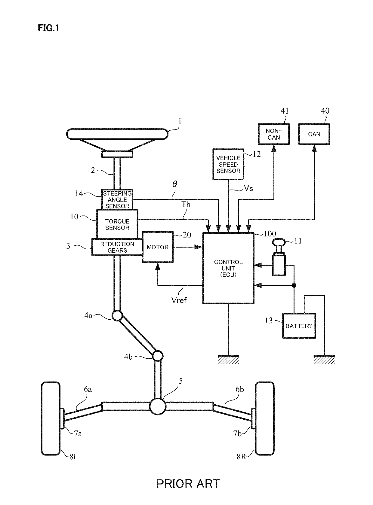
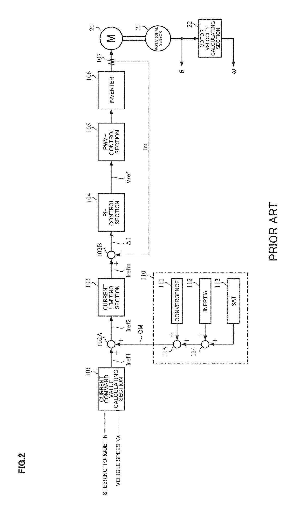
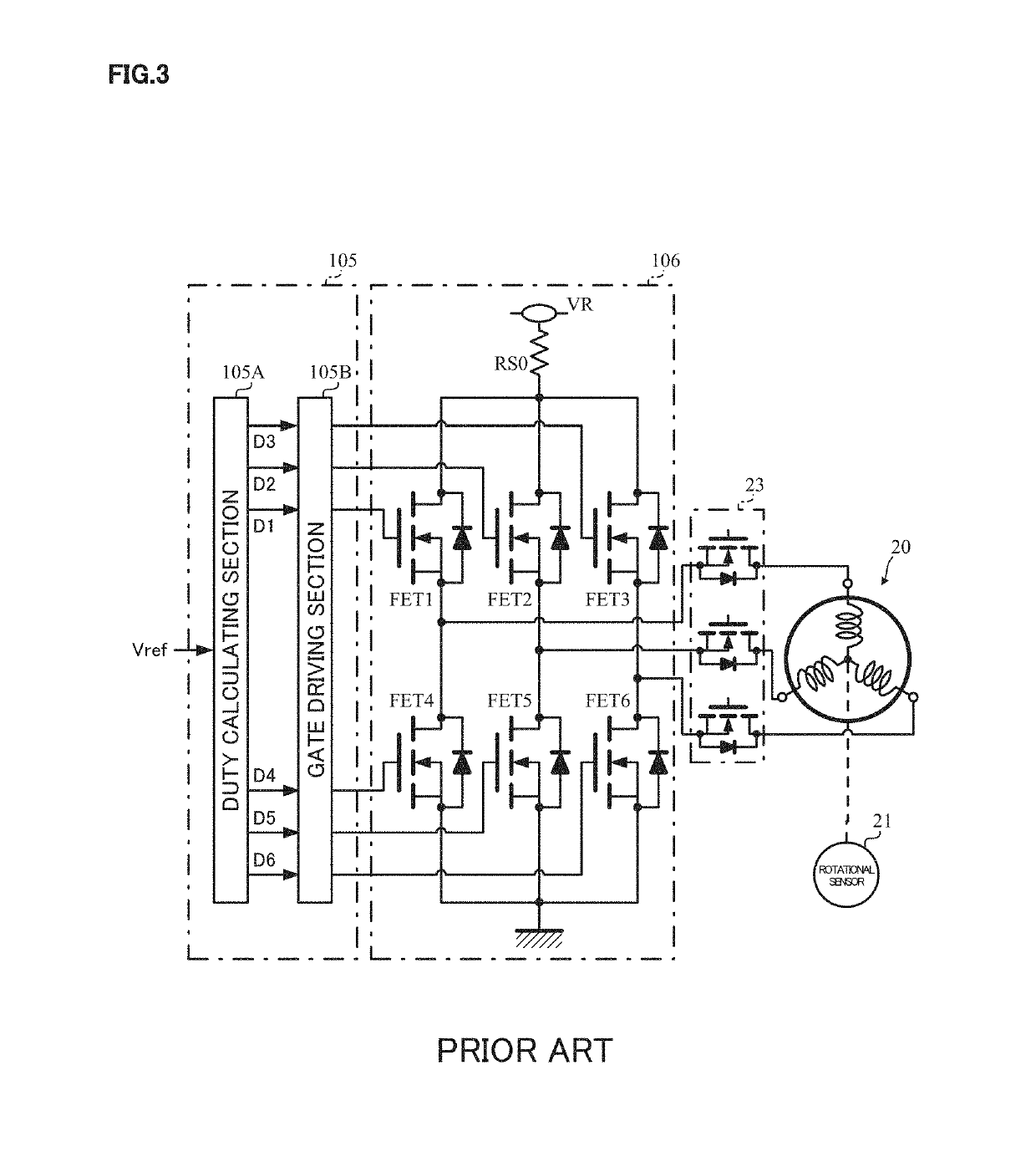
TECHNICAL FIELD[0001]The present invention relates to a motor control unit that surely protects semiconductor switching devices (for example, field-effect transistors (FETs)) by turning-OFF a motor release switch, which comprises the semiconductor switching devices connected to an inverter which drives the motor, when a switching loss in blocking the switching devices by generating from the regenerative electric power continues for a predetermined time in a state that a rotational speed is equal to or lower than that of an area of safety operation by using energy (electric power) of regenerative electric power (which is obtained from a motor back-electromotive force voltage (a motor back-EMF) and a regenerative current) and a temperature by a motor rotation when the motor rotates by means of an external force, and an electric power steering apparatus equipped with the above motor control unit.[0002]The electric power steering apparatus applies a steering assist torque to a steering ...

Claims


Application Information

Patent Timeline
IPC IPC(8): B62D5/04H02P6/08H02P6/28H02P23/14
CPCB62D5/0463B62D5/0409B62D5/0481H02P6/08H02P6/28H02P23/14B62D5/0484B62D5/0487B62D5/0496H02P29/024H02P6/12
Inventor KOGURE, TERUYOSHISHIMAKAWA, SHIGERUKUMAGAI, SHINSUZUKI, RYOICHI
Owner NSK LTD
Learn More