

Piston for an internal combustion engine
a technology for internal combustion engines and pistons, which is applied to pistons, machines/engines, engine components, etc., can solve the problems of affecting the function of pistons, degrading the efficiency and emissions of the associated internal combustion engines, etc., and achieves the reduction of temperature below the piston crown, reducing carbon deposits, and increasing oil life
- Summary
- Abstract
- Description
- Claims
- Application Information
AI Technical Summary
Benefits of technology
Problems solved by technology
Method used
Image

Examples
Embodiment Construction
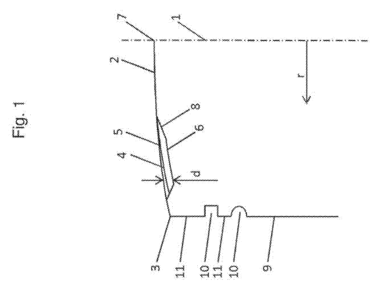
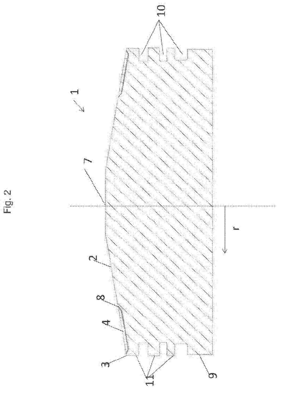
[0022]FIG. 1 shows a schematic representation of a piston 1 in cross-section for orientation and naming of the components. The piston 1 has a piston crown 2 and a crown edge 3. At the part adjacent to the crown edge 3 of the lateral surface of the piston 1, the piston skirt 9, fire lands 11 are formed. These are the areas between which the annular grooves 10 for receiving piston rings are located. A thermal barrier coating 4 extends, starting near the outer periphery of the piston 1, i.e. near the crown edge 3 in the direction of the center 7 of the piston 1. In the exemplary embodiment shown, the thermal barrier coating 4 has an adhesion promoter layer 6 and a cover layer 5. The thickness of the thermal barrier coating 4 is indicated by the reference sign d. The thermal barrier coating 4 extends as a circumferential ring or seam on the piston crown 2 to near an edge 8. More particularly, the thickness d of the thermal barrier coating 4 decreases in a region of the edge 8, resulting...
PUM
 Abstract
Description
Claims
Application Information