Image acquiring device and method of correcting coordinates thereof

a technology of image acquisition and coordinates, which is applied in the field of coordinate correction, can solve the problems of low efficiency of the repair process, the damage of the prior art photographing and repairing process, and the influence of the liquid crystal display panel, so as to improve the efficiency of the subsequent repairing process, reduce equipment depreciation, and facilitate operation

Active Publication Date: 2019-03-28
CHONGQING HKC OPTOELECTRONICS TECH CO LTD +1
View PDF0 Cites 7 Cited by
  • Summary
  • Abstract
  • Description
  • Claims
  • Application Information

AI Technical Summary

Benefits of technology

[0026]In the present application, after acquiring a coordinate of a defect detected by a preprocessing; initializing a position of a photographing device according to the coordinate of the defect detected in the preprocessing at first, and then adjusting the position of the photographing device according to a position of the defect in the picture currently captured by the photographing device, so that the defect is located at the center of the picture currently captured by the photographing device; recording the coordinate of the defect at the center of the pictu...

Problems solved by technology

In a manufacturing process of a liquid crystal display panel, the liquid crystal display panel may be affected by a defect at a substrate itself or the defect introduced in the manufacturing process.
However, a photographing and repairing process in the prior art has following problems.
On one hand, if the color film camera moves to the position of the defect according to the coordinate of the defects uploaded by the AOI and takes a picture, the defect may not be at a center of visual field due to ...

Method used


Image

  • Image acquiring device and method of correcting coordinates thereof
  • Image acquiring device and method of correcting coordinates thereof
  • Image acquiring device and method of correcting coordinates thereof

Examples


Embodiment Construction

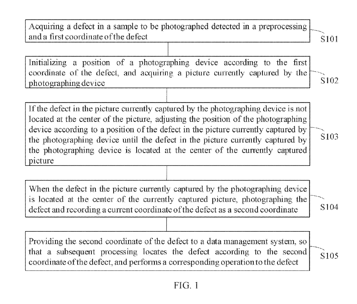
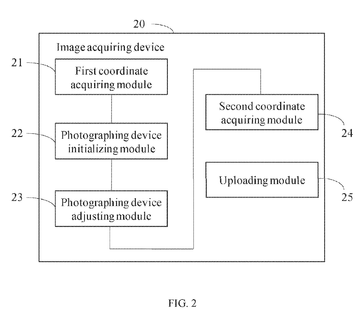
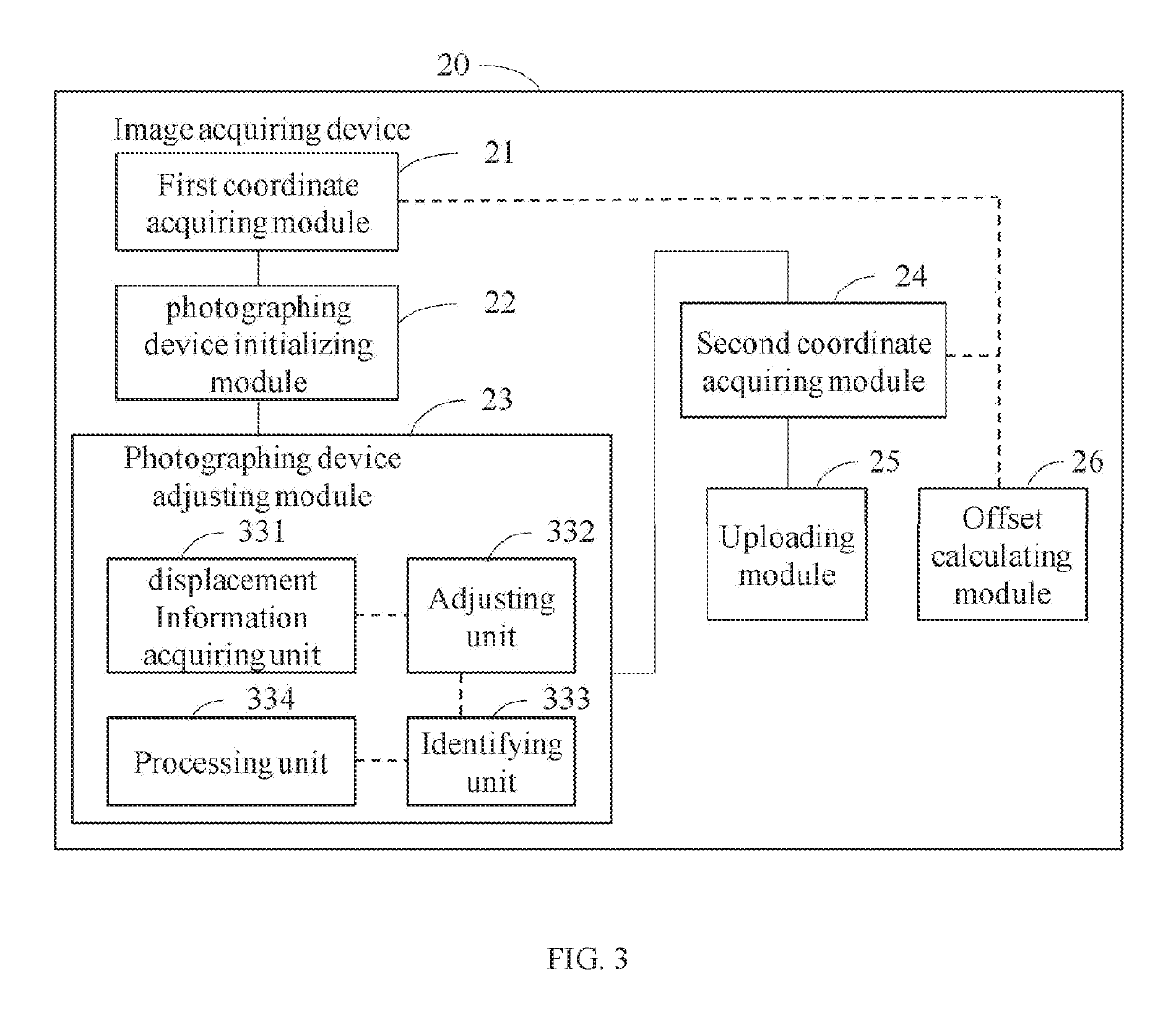
[0032]The technical solutions in embodiments of the present application are clearly and completely described below with reference to the accompanying drawings in the embodiments of the present application. Apparently, the described embodiments are merely a part of the embodiments of the present application, but not all of the embodiments. All other embodiments obtained by those skilled in the art based on the embodiments of the present application without creative efforts shall fall within the protecting scope of the present application.

[0033]It should be understood that the term “comprise”, which is used in specification and appended claims, indicates the presence of the stated feature, integer, step, operation, element, and / or component, but does not exclude the presence or addition of one or more other features, integers, steps, operations, elements, and / or components.

[0034]It should also be understood that the terms used herein in the specification of the present application are...


PUM


Abstract

The present application provides an image acquiring device and a method of correcting coordinates of the image acquiring device, wherein the method includes: detecting a coordinate of a defect detected in a process; initializing a position of a photographing device according to the coordinate of the defect detected in a preprocessing; then adjusting the position of the photographing device according to a position of the defect in the picture currently captured by the photographing device, so that the defect is located at the center of the picture currently captured by the photographing device; recording the coordinate of the defect at the center of the picture; and providing the coordinate of the defect at the center of the picture to a data management system.

Description

FIELD OF THE INVENTION[0001]The present application relates to the technical field of coordinate correction, and more particularly relates to an image acquiring device and a method of correcting coordinates of the image acquiring device.BACKGROUND OF THE INVENTION[0002]In a manufacturing process of a liquid crystal display panel, the liquid crystal display panel may be affected by a defect at a substrate itself or the defect introduced in the manufacturing process. An Automatic Optical Inspection (AOI) machine is usually adopted to detect a defect in a sample to be photographed based on optical principles. If the AOI machine detects the defect, it will record a coordinate of the defect and upload the coordinate of the defect to a Manufacturing Execution System (MES). After loading the sample to be photographed at a color film camera, the color film camera downloads the coordinate of the detect uploaded by the AOI machine from the MES, and then directly moves to the coordinate to pho...

Claims


Application Information

Patent Timeline
IPC IPC(8): G06T7/00G06T7/70H04N5/232
CPCG06T7/0004G06T7/70H04N5/23299G06T2207/30121G06T2207/30244G06T7/0008G09G3/006G06T2207/30108H04N23/80H04N23/61H04N23/695
Inventor FENG, HU
Owner CHONGQING HKC OPTOELECTRONICS TECH CO LTD
Why Eureka
Try Eureka