Water level monitoring system

a monitoring system and water level technology, applied in the field of water level gauges, can solve the problems of flood disaster, easy damage to the sensing mechanism, easy impact on the non-contact type, etc., and achieve the effect of expanding the measurable rang

Inactive Publication Date: 2019-04-04
NAT APPLIED RES LAB
View PDF4 Cites 2 Cited by
  • Summary
  • Abstract
  • Description
  • Claims
  • Application Information

AI Technical Summary

Benefits of technology

[0005]An object of the invention is to provide a water level monitoring system, which utilizes modularization and series connection to extend a measurable range and to overcome the inherent problem of the contact type. As a result, the invention can implement a monitoring system with continuity and individual monitor.

Problems solved by technology

This usually causes disaster of floods.
However, the non-contact type is easy to be affected by the environment because of physical limitations and is relatively expensive.
The contact type is cheaper than the non-contact type, but its sensing mechanism is easy to be damaged due to collision with foreign matter in water.
In other words, two existing types of water level gauges are not good enough.
This is a problem to be solved.

Method used


Image

  • Water level monitoring system
  • Water level monitoring system
  • Water level monitoring system

Examples


second embodiment

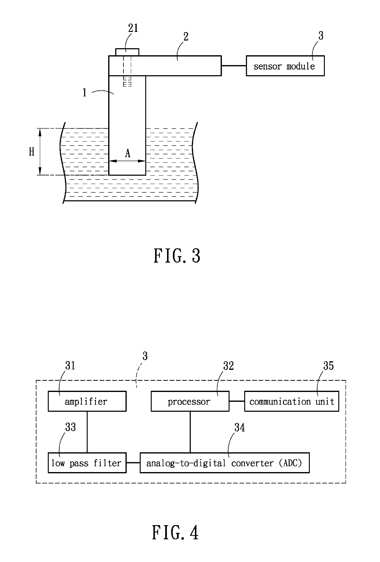
[0016]Please refer to FIG. 4, which is a block diagram of circuit of the invention. As shown, the sensor module 3 includes a low pass filter 33 and an analog-to-digital converter (ADC) 34. The analog-to-digital converter 34 is electrically connected to the low pass filter 33. The low pass filter 33 is used for filtering the sensed value from the amplifier 31 to reduce noise. The ADC 34 is electrically connected between the low pass filter 33 and the processor 32 for converting the sensed value from the low pass filter 33 into a digital format and then sending back to the processor 32 for further calculation. In addition, the processor 32 is further electrically connected to a communication unit 35 through which the processor 32 can transmit its sensing information to an external system via network for remote control and sequential analysis.

third embodiment

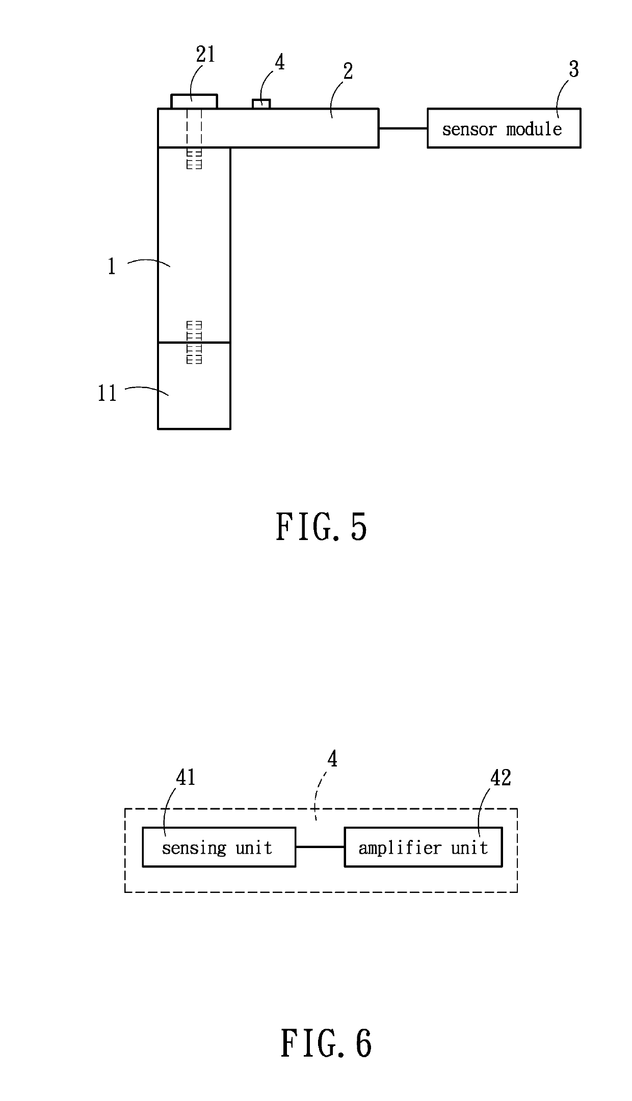
[0017]Please refer to FIG. 5, which is a schematic view of structure of the invention. As shown, a temperature sensing module 4 is disposed on the load cell 2. The temperature sensing module 4 includes a sensing unit 41 and an amplifier unit 42. As shown in FIG. 6, the sensing unit 41 is electrically connected to the amplifier unit 42. The temperature sensing module 4 is electrically connected to the sensor module 3. The sensing unit 41 is used for sensing an environmental temperature and a temperature of the load cell 2 and sending the sensed temperature values amplified by the amplifier unit 42 back to the processor 32 of the sensor module 3. As a result, the sensed values of the load cell 2, which are affected by temperature, can be corrected. In this embodiment, the sensing unit 41 is a temperature detector. Additionally, the floating unit 1 can be added with a first floater 11 for extending length of the whole floater. This can satisfy different requirements under various measu...


PUM


Abstract

A water level monitoring system includes at least one floating unit, a load cell and a sensor module. The floating unit is used for sinking in water. The load cell is connected to the floating unit for generating a force value reflecting buoyancy generating from the floating unit entering the water. The sensor module is connected to the load cell for sensing the force value from the load cell and includes an amplifier for amplifying a sensed value. A processor connected to the amplifier receives the sensed value from the amplifier and calculating a water level depth to be measured. Thus the water level motoring system has features of low cost, high stability and flexibility.

Description

BACKGROUND OF THE INVENTION1. Technical Field[0001]The invention relates to water level gauges, particularly to a water level monitoring system which uses buoyancy to calculate water level depth.2. Related Art[0002]In recent years, due to global warming and extreme weather, heavy rain occurs more and more frequently and seriously. This usually causes disaster of floods.[0003]To increase an effect of early warning, systems of early warning for flood are built by the governments for warning people to prevent disaster. These systems are usually disposed at embankments or water gates. However, some floods in urban areas are irrelated to the water depth information in those places. Therefore, quantity and location of disposition of the water level gauges are a key component to improve the definition and accuracy of the systems.[0004]Conventional water level gauges can be roughly divided into two kinds, namely, non-contact type and contact type. The non-contact type, such as an ultrasonic...

Claims


Application Information

Patent Timeline
Patent Type & Authority Applications(United States)
IPC IPC(8): G01F23/00
CPCG01F23/0038G01F23/80
Inventor HUANG, CHUN-MINGCHEN, CHEN-CHIAWU, CHIEN-MING
Owner NAT APPLIED RES LAB
Why Eureka
Try Eureka