
Vertical cavity surface emitting laser including meta structure reflector and optical device including the vertical cavity surface emitting laser

a vertical cavity surface and emitting laser technology, applied in semiconductor lasers, instruments, optical elements, etc., can solve the problems of low thermal conductivity (or high thermal resistance) of dbr and attenuation of the oscillation efficiency of vcsel

Active Publication Date: 2019-04-04
SAMSUNG ELECTRONICS CO LTD
View PDF4 Cites 2 Cited by
  • Summary
  • Abstract
  • Description
  • Claims
  • Application Information

AI Technical Summary

Benefits of technology

This patent describes a type of laser that can efficiently cool itself. It uses a special design that allows light to be emitted through multiple reflectors, which helps to dissipate the heat that is generated inside the laser. This results in a more powerful, reliable laser that can be used in a variety of applications.

Problems solved by technology

Also, the DBR has low thermal conductivity (or high thermal resistance) due to phonon scattering that occurs at an interface between two materials.
Thus, when a current is applied to the VCSEL including the DBR for oscillation, internally generated self-heating is not effectively dissipated, and thus, the oscillation efficiency of the VCSEL may be attenuated.
Also, the exemplary embodiments are not required to overcome the disadvantages described above, and may not overcome any of the problems described above.

Method used


Image

  • Vertical cavity surface emitting laser including meta structure reflector and optical device including the vertical cavity surface emitting laser
  • Vertical cavity surface emitting laser including meta structure reflector and optical device including the vertical cavity surface emitting laser
  • Vertical cavity surface emitting laser including meta structure reflector and optical device including the vertical cavity surface emitting laser

Examples


Embodiment Construction

[0053]Exemplary embodiments are described in greater detail below with reference to the accompanying drawings.

[0054]In the following description, like drawing reference numerals are used for like elements, even in different drawings. The matters defined in the description, such as detailed construction and elements, are provided to assist in a comprehensive understanding of the exemplary embodiments. However, it is apparent that the exemplary embodiments can be practiced without those specifically defined matters. Also, well-known functions or constructions are not described in detail since they would obscure the description with unnecessary detail. Expressions such as “at least one of,” when preceding a list of elements, modify the entire list of elements and do not modify the individual elements of the list.

[0055]An expression such as “above” or “on” may include not only the meaning of “immediately on in a contact manner”, but also the meaning of “on in a non-contact manner”.

[0056...


PUM


Abstract

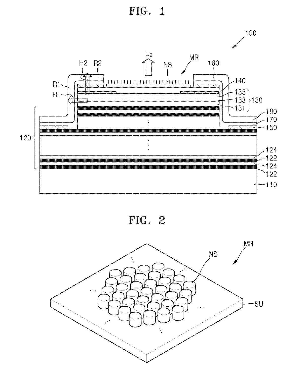
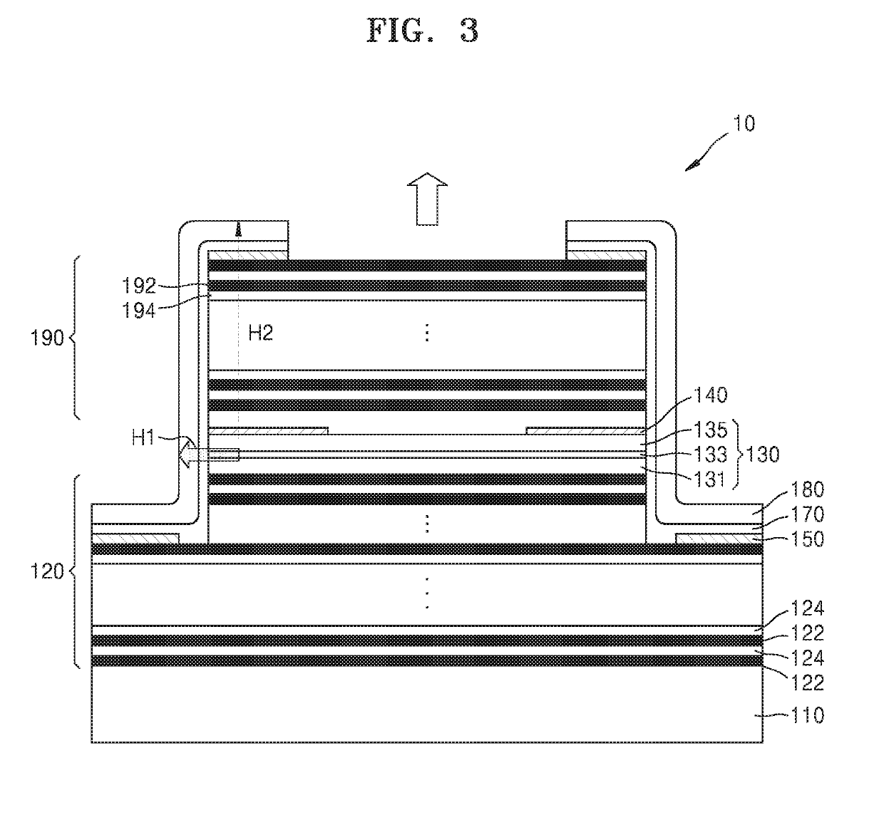
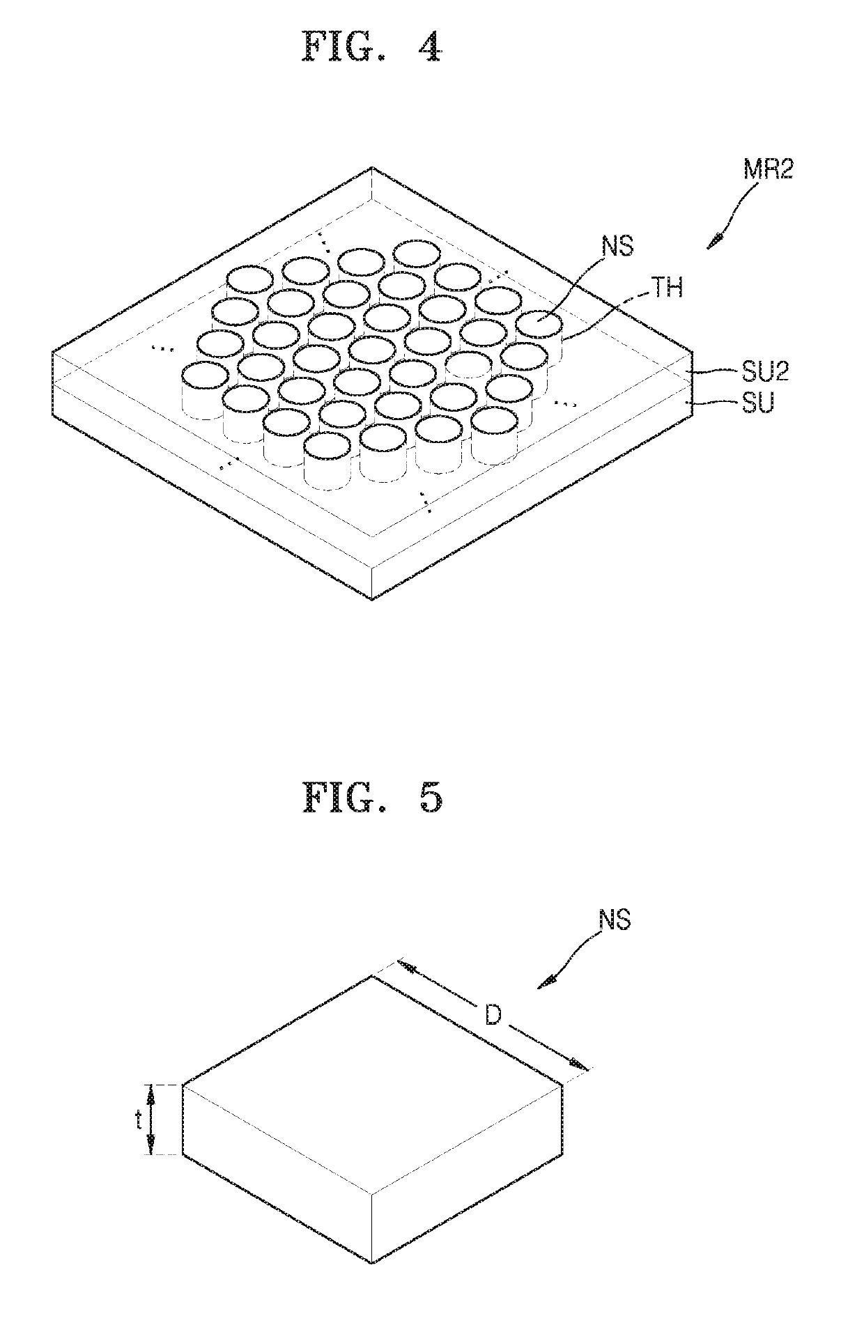
A vertical cavity surface emitting laser includes a gain layer configured to generate light; a distributed Bragg reflector below the gains layer; and a meta structure reflector above the gain layer and comprising a plurality of nano structures having a sub wavelength dimension.

Description

CROSS-REFERENCE TO RELATED APPLICATIONS[0001]This application is a continuation-in-part of U.S. application Ser. No. 15 / 804,537, filed on Nov. 6, 2017, which claims priority from Korean Patent Application No. 10-2017-0036920, filed on Mar. 23, 2017, in the Korean Intellectual Property Office, the disclosures of which are incorporated herein by reference in their entireties.BACKGROUND1. Field[0002]Apparatuses and methods consistent with exemplary embodiments relate to a vertical cavity surface emitting laser including a meta structure.2. Description of the Related Art[0003]Vertical cavity surface emitting lasers (VCSELs), unlike edge emitting lasers (EELs), have low power consumption because of a short optical gain length. Also, the VCSELs facilitate high density integration and mass production since they are manufactured as 2D arrays because of vertical emission. While the conventional EEL is asymmetrical with respect to an optical output, the VCSEL can operate in a circular symmetr...

Claims


Application Information

Patent Timeline
IPC IPC(8): H01S5/183H01S5/042H01S5/187H01S5/024G02B27/28G01B11/24G01D5/30
CPCH01S5/18361H01S5/0425H01S5/187H01S5/02469G02B27/283G01B11/24G01D5/30H01S5/343H01S5/18355H01S5/18386G01B11/25H01S5/18347H01S5/04257
Inventor NA, BYUNGHOONHAN, SEUNGHOON
Owner SAMSUNG ELECTRONICS CO LTD
Learn More