Mailbox Punching Device

a punching device and box technology, applied in the field of mailboxes, can solve the problems of reducing work achieve the effects of improving punching efficiency and punching quality, simple structure, and convenient us

Inactive Publication Date: 2019-04-11
NANTONG WEIXING TEXTILE TECH CO LTD
View PDF0 Cites 9 Cited by
  • Summary
  • Abstract
  • Description
  • Claims
  • Application Information

AI Technical Summary

Benefits of technology

[0012]The invention has simple structure and it is convenient to use. The first steering cavity with the opening facing downward is set at the bottom of the box. The second steering cavity is up and down extended in the box above the first steering cavity. The first sliding groove is connectedly set on the one inner wall of the second steering cavity, and the steering platform, through bearings, is rotatably mounted in the first steering cavity. The first steering shaft which extends into the second steering cavity, is fixedly arranged on the top of said steering platform, and the first cone pulley is fixedly mounted on the first steering shaft in the second steering cavity. The first sliding groove is provided with the first sliding block that can be up and down slidably connected. The first sliding block is provided with the first screw hole, and the first screw bolt is cooperatively mounted in the first screw hole. The bottom of the first screw bolt is rotatably set in the inner bottom wall of the first sliding groove, and the top of the first screw bolt is in power connection with the first motor which is fixedly set in the inner top wall of the first sliding groove. The second motor, one side of which is in power connection with the second steering shaft extending to the second steering cavity, is set in one end face of the first sliding block. The second steering shaft in the second steering cavity is fixedly provided with the second cone pulley cooperatively connected to the first cone pulley, and the box above the second steering cavity is provided with the third steering cavity which is rotatably provided with the toothed connecting gear through the third steering shaft. The third cone pulley, which is cooperatively connected with the toothed connecting gear, is rotatably mounted on the inner bottom wall of the third steering cavity, and the third steering shaft extending into the second steering cavity is fixedly set at the bottom end face of the third cone pulley. The third steering shaft in the second steering cavity is fixedly provided with the fourth cone pulley matched with the second cone pulley, wherein the inner top wall of said third steering cavity is provided with a sliding cavity which extends to two sides and passes through the two sides of said box, and the sliding arm is slidably mounted on the sliding cavity. The top end face of the sliding arm is fixedly provided with the toothed connecting strip which is cooperatively connected with the toothed connecting gear, so as to punch quickly and to adjust hole distance, which can greatly improve the punching efficiency and the punching quality.

Problems solved by technology

In the traditional case, the mailbox punching device only has a simple drilling function, and the adjustment and control towards hole distance relies on excessive manpower, which greatly reduces work efficiency and the quality of punching.

Method used


Image

  • Mailbox Punching Device
  • Mailbox Punching Device

Examples


Embodiment Construction

[0017]All of the features disclosed in this specification, or all of the methods or procedures in the process disclosed, may be combined in any way other than mutually exclusive features and / or steps.

[0018]Any feature disclosed in this specification (including any additional claims, abstract and drawings) may be replaced by other equivalent or alternative features with similar purposes, unless otherwise stated. That is, unless otherwise stated, each feature is just one example of a series of equivalent or similar features.

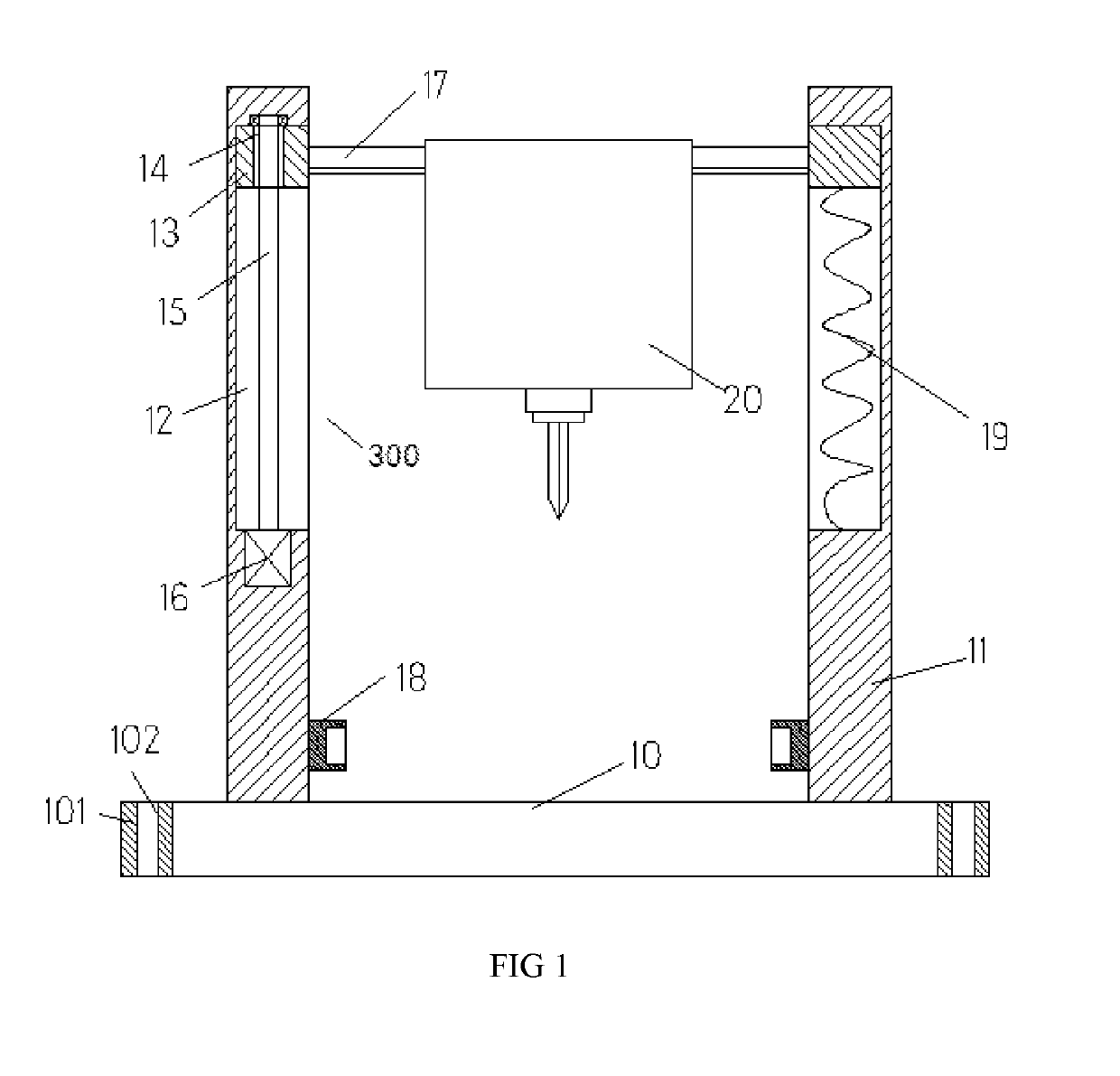
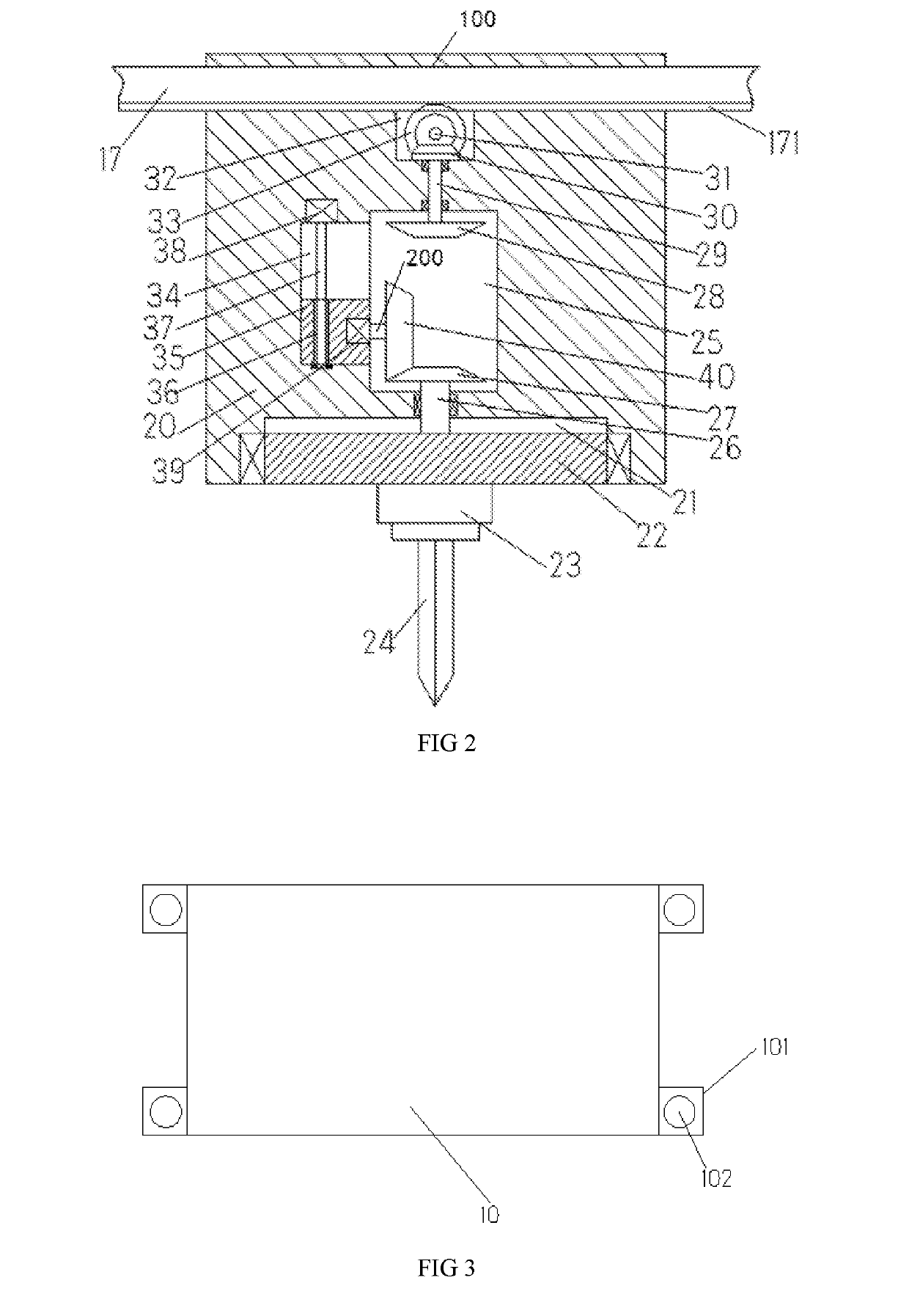
[0019]Referring to FIG. 1-3, a mailbox punching device of the present invention comprises a baseplate 10, frames 11 which are correspondingly arranged at the two ends of the top of said baseplate 10, and a box 20 arranged between two said frames 11 on the two ends through a lifting device, wherein the two end faces of said baseplate 10 are simultaneously provided with a fixing block 101, and said fixing block 101 is provided with a fixing hole 102, and said basepla...


PUM

PropertyMeasurementUnit
distanceaaaaaaaaaa
structureaaaaaaaaaa
stabilityaaaaaaaaaa

Abstract

The invention discloses a mailbox punching device, comprising a baseplate, two frames which are correspondingly arranged at the two ends of the top of the baseplate, and a box arranged between the two frames on the two ends through a lifting device. The inner bottom of the box is provided with a first steering cavity with a an opening facing downward, and a second steering cavity extends vertically is up and down extended in the box above the first steering cavity. A first sliding groove is connectedly set on the one inner wall of a the second steering cavity, and a steering platform, through bearings, is rotatably mounted in the first steering cavity. A first steering shaft which extends into the second steering cavity, is fixedly arranged on the top of the steering platform, and a first cone pulley bevel gear is fixedly mounted on the first steering shaft in the second steering cavity.

Description

CROSS-REFERENCES TO RELATED APPLICATIONS[0001]The present application claims priority from Chinese application No. 201810238351.4 filed on Mar. 22, 2018 which is hereby incorporated herein by reference in its entirety.TECHNICAL FIELD[0002]The invention relates to the field of mailbox, in particular to a mailbox punching device.BACKGROUND OF THE INVENTION[0003]A mailbox is an important storage tool for mail delivery and it is widely used in real life. During manufacturing process of the mailbox, mailbox plates are needed to be punched to facilitate the quick assembly between the various parts of mailbox plates. In the traditional case, the mailbox punching device only has a simple drilling function, and the adjustment and control towards hole distance relies on excessive manpower, which greatly reduces work efficiency and the quality of punching.BRIEF SUMMARY OF THE INVENTION[0004]The aim of the invention is to provide a malibox punching device so as to overcome the problems existing...

Claims


Application Information

Patent Timeline
Patent Type & Authority Applications(United States)
IPC IPC(8): B26F1/16
CPCB23B39/14Y10T408/65B23Q1/0054B26F1/16B23B39/04Y10T408/91Y10T408/6793B23B39/006B23B47/26B26D5/086B26D7/2628B26F1/14
Inventor SHU, YONGJUN
Owner NANTONG WEIXING TEXTILE TECH CO LTD
Why Eureka
Try Eureka