Ion wind generation device

a generation device and ion wind technology, applied in the direction of corona discharge, energy input, oxygen/ozone/oxide/hydroxide, etc., can solve the problems of affecting the work of housewives and relevant workers, affecting the comfort or burden of caregivers and the ambient, and releasing the offensive odor around the garbage disposal during operation. a very serious problem

Active Publication Date: 2019-04-18
KATANO IND
View PDF2 Cites 8 Cited by
  • Summary
  • Abstract
  • Description
  • Claims
  • Application Information

AI Technical Summary

Benefits of technology

[0020]A wide range of ion delivery can be provided and ion wind can be provided wit

Problems solved by technology

However, the offensive odor that is released every time the box is opened gives a discomfort or burden to a caregiver and the ambient, and also it is unsanitary.
In homes and restaurants where garbage storage boxes are present, the offensive odor caused by growth of bacteria that is released every time the boxes are opened also puts a large burden on housewives and relevant workers.
As the use of garbage disposer increases due to development of biotechnology, offensive odor released around the garbage disposer during operation has become a very serious problem.
However, residual odor of loaded products and musty odor in air conditioners have become problematic.
Further, air conditioners for storehouses, refrigerators, or indoor/in-vehicle spaces have the problem of offensive odor depending on the usage conditions of stored materials.
However, when such a simplified sterilizer/deodorizer is used in a waste box or a garbage storage box, offensive odor is released when the box is opene

Method used


Image

  • Ion wind generation device
  • Ion wind generation device
  • Ion wind generation device

Examples


first embodiment

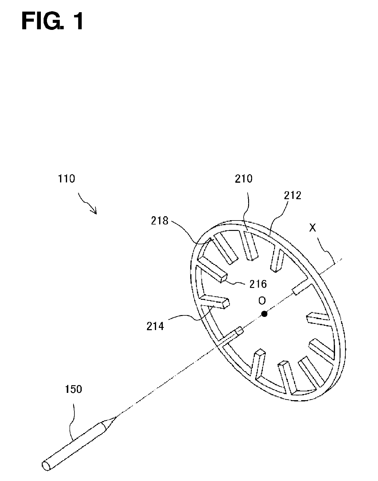
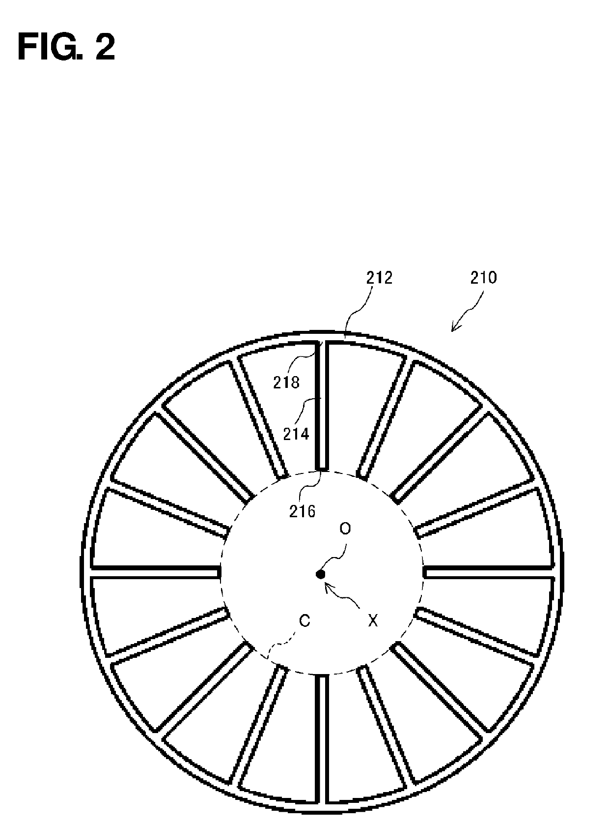
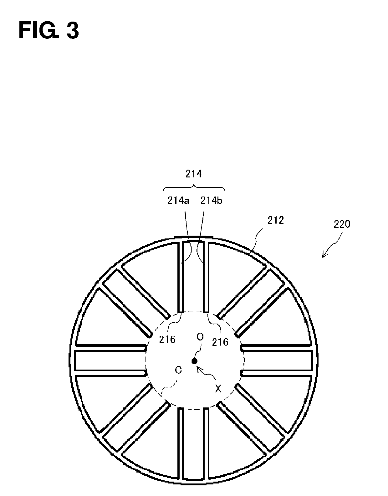
[0084]As illustrated in FIG. 1, an ion wind generation device 110 according to the first embodiment includes an electrode pair of a discharge electrode body 150 and any of counter electrode bodies 210 to 510. The discharge electrode body 150 and any of the counter electrode bodies 210 to 510 include an electrical conductor such as metal. The ion wind generation device 110 of the first embodiment can selectively include any one of the counter electrode bodies 210 to 510. Each of the counter electrode bodies 210 to 510 has the corresponding shape illustrated in FIGS. 2 to 18.

[0085]The principle of the ion generation of the ion wind generation device 110 of the first embodiment is similar to that of the existing ion wind generation device. That is, a potential difference is generated between the discharge electrode body 150 and the counter electrode body 210 to 510 causes corona discharge to occur between these electrodes. During corona discharge, ions released from the discharge elect...

second embodiment

[0197]In the ion wind generation device 110 according to the above-described first embodiment, the description has been made of the configuration that the discharge electrode body 150 faces one side (front side) of the counter electrode body 210 and the like, and ion wind is generated from the one side (front side) toward the other side (back side) of the counter electrode body 210 and the like. Such an overall unidirectional flow of ion wind from the front side toward the back side enables the ion wind to be scattered farther. However, when the ion wind is desirably to be scattered to spread over in a substantially radial direction (over 360 degrees) in a space, another configuration different from the ion wind generation device 110 according to the first embodiment may be preferable.

[0198]Such an ion wind generation device is described hereinafter as a second embodiment. As illustrated in FIGS. 23 to 25, an ion wind generation device 120 according to the present inventions include...

third embodiment

[0233]The ion wind generation device 110 according to the first embodiment and the ion wind generation device 120 according to the second embodiment have been described in detail as different embodiments capable of reducing generation of ozone included in the ion wind by providing an annular-like counter electrode body with a particular shape. The following description is an ion wind generation device 130 according to the third embodiment having a non-annular type of counter electrode body.

[0234]The above-described example shows that the electrode body of the receiving electrode that is the counter electrode body has a substantially annular shape. The electrode body of the receiving electrode may have a linear shape. In this case, the electrode body of the discharging electrode may also have a linear shape in accordance with the shape of the electrode body of the receiving electrode.

[0235]As illustrated in FIGS. 26A and 26B, the ion wind generation device 130 of the present inventio...


PUM


Abstract

Provided is an ion wind generation device which is capable of providing a wide range of ion delivery and providing ion wind having a reduced ozone concentration near a nozzle without use of a filter or the like.
The ion wind generation device includes an electrode pair including a discharge electrode body having a discharge portion and a counter electrode body having a plurality of end portions, and generates ion wind by corona discharge that occurs due to a potential difference generated between the discharge portion and the end portions. The end portions are located spaced apart from one another in a single plane and disposed around an axis of the discharge electrode body in the single plane or disposed along a line in the single plane.

Description

TECHNICAL FIELD[0001]The present invention relates to a device for generating ion wind by corona discharge. More particularly, the present invention is directed to an ion wind generation device capable of providing ion wind having a reduced ozone concentration. Further, in a certain aspect, the present invention relates to a device and method for sterilizing and deodorizing a target object such as waste, and in particular, to a device and method for sterilizing and deodorizing the target object by causing corona discharge to occur in a space that is separate from a space in which the target object is placed, generating ions, and supplying ion wind to the space in which the target object is placed. More specifically, the present invention relates to an environmental device for sterilization and deodorization, designed to be equipped at a high airtight box, for example, a disposal box for garbage, diaper or the like, a box for a disposed odor of a garbage disposer, a box for receiving...

Claims


Application Information

Patent Timeline
IPC IPC(8): B01J19/08C01B13/11A61L2/20A61L2/14A61L9/04A61L9/22H01T23/00H01T19/04
CPCB01J19/088C01B13/115A61L2/202A61L2/14A61L9/046A61L9/22H01T23/00H01T19/04C01B2201/22B01J2219/0849B01J2219/0833B01J2219/0896A61L11/00A61L2202/11A61L2202/25A61L2209/16A61L2209/212C01B13/11C01B2201/62Y02P20/133A61L9/015
Inventor KATANO, AKIO
Owner KATANO IND
Why Eureka
Try Eureka