Wound rotor motor for vehicle

a technology for rotor motors and vehicles, applied in the direction of synchronous motors, electric devices, propulsion by batteries/cells, etc., can solve the problems of reducing the operation efficiency of the motor, affecting the cooling effect of the motor, and the friction loss of the rotor, so as to achieve the effect of improving the cooling

Active Publication Date: 2019-04-18
HYUNDAI MOTOR CO LTD +1
View PDF5 Cites 3 Cited by
  • Summary
  • Abstract
  • Description
  • Claims
  • Application Information

AI Technical Summary

Benefits of technology

[0006]The present invention provides a wound rotor motor for a vehicle, in which a rotary shaft, which operates as the rotational center of a rotor, is disposed in the vertical direction of a vehicle when mounted thereto, to immerse a plurality of lower coil portions arranged in the circumferential direction of a stator and a pl

Problems solved by technology

Thus, the wound rotor motor is not properly cooled.
However, spraying cooling oil onto the motor incre

Method used


Image

  • Wound rotor motor for vehicle
  • Wound rotor motor for vehicle
  • Wound rotor motor for vehicle

Examples


first embodiment

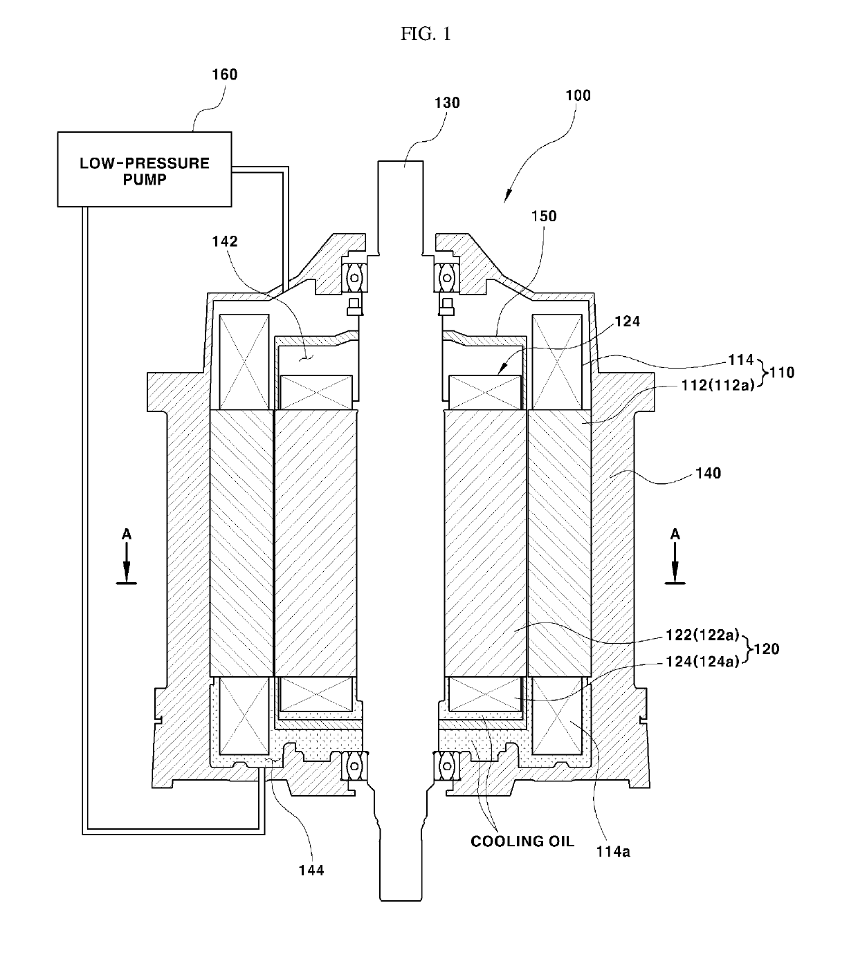
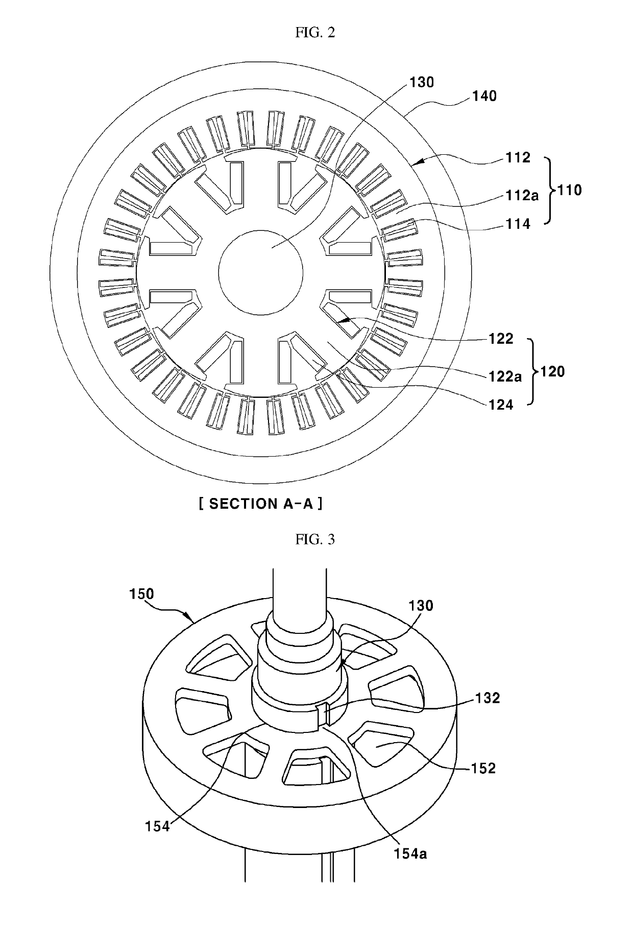
[0029]FIG. 1 is a view illustrating a wound rotor motor according to the first exemplary embodiment of the present invention, FIG. 2 is a sectional view taken along line A-A in FIG. 1, and FIG. 3 is a view illustrating an upper plate coupled to a rotary shaft of the wound rotor motor according to the first exemplary embodiment of the present invention.

[0030]The first exemplary embodiment of the present invention may include a rotary shaft 130, which operates as a rotational center of a rotor 120, disposed in the vertical direction of a vehicle to be perpendicular to the axial direction of wheels (e.g., drive wheels that rotate by receiving driving torque from the electric motor) of the vehicle, whereby a plurality of lower coil portions 114a provided at a stator 110 and a plurality of lower coil portions 124a provided at the rotor 120 may be immersed to a predetermined depth in cooling oil.

[0031]As shown in FIGS. 1 and 2, a wound rotor motor 100 according to the first exemplary embo...

second embodiment

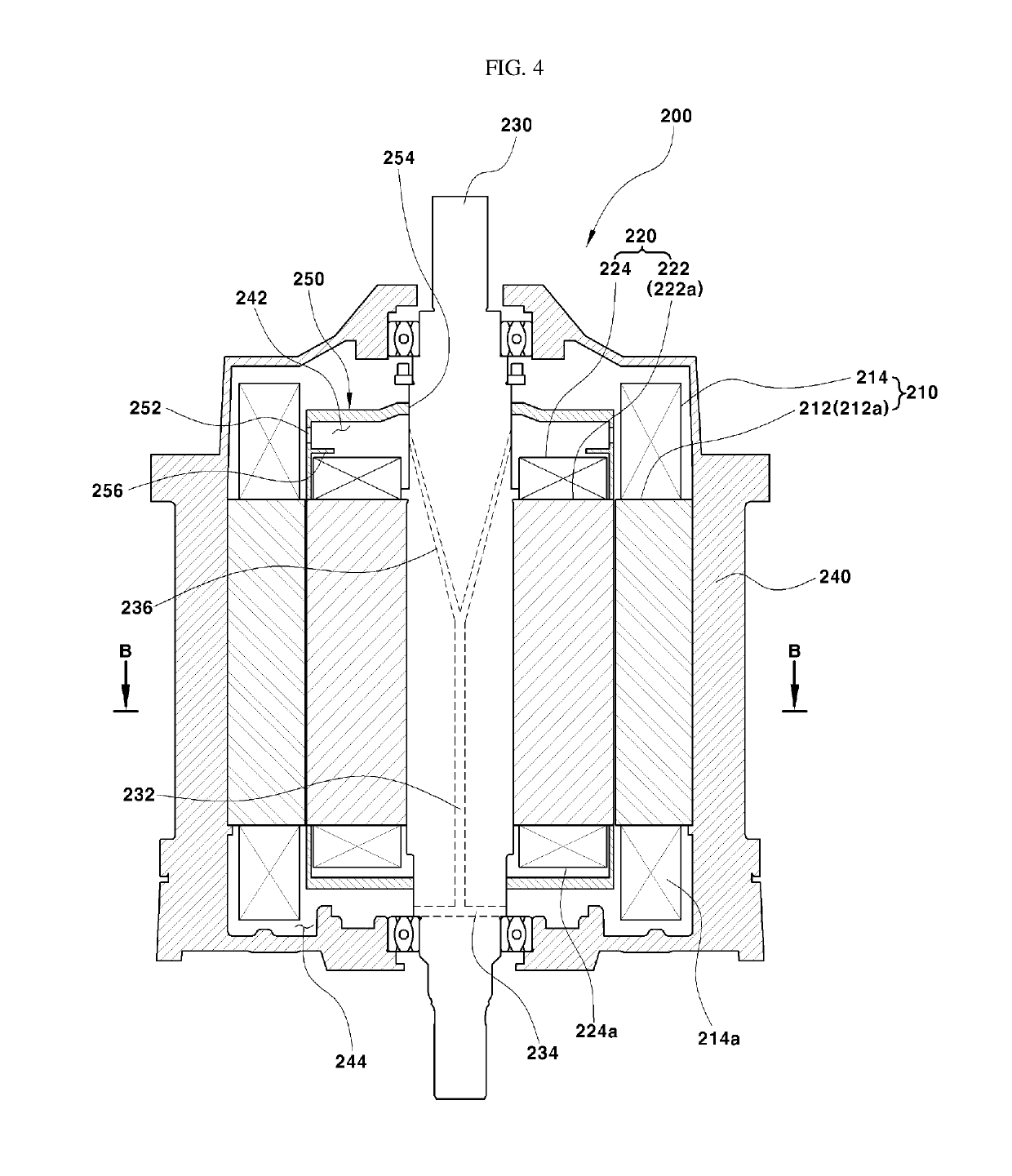
[0045]FIG. 4 is a view illustrating the wound rotor motor according to the second exemplary embodiment of the present invention, FIG. 5 is a sectional view taken along line B-B in FIG. 4, FIG. 6 is a view illustrating an upper plate of the wound rotor motor according to the second exemplary embodiment of the present invention, FIG. 7 is a view schematically showing the flow path of cooling oil of the wound rotor motor according to the second exemplary embodiment of the present invention, and FIG. 8 is a view showing the flow of the cooling oil within the upper plate according to the second exemplary embodiment of the present invention.

[0046]The second exemplary embodiment of the present invention may include a rotary shaft 230, which operates as a rotational center of a rotor 220, may be arranged in the vertical direction of a vehicle to be perpendicular to the axial direction of wheels of the vehicle, and a flow passage 232 may be formed inside the rotary shaft 230 to move or guide...


PUM


Abstract

A wound rotor motor is provided, in which a rotary shaft is arranged in the vertical direction, to immerse lower coil portions of a stator and a rotor in cooling oil, thereby improving the cooling effect beyond that of a conventional configuration, in which lower coil portions are partially immersed, and consequently decreasing the capacity of an oil pump. A wound rotor motor is provided, in which a rotary shaft is arranged in the vertical direction and has therein a flow passage, through which cooling oil moves up from the region below the rotor and is sprayed to the region above the rotor by centrifugal force generated by rotation of the rotor, thereby enhancing the motor-cooling effect, decreasing the frictional loss of the rotor due to the cooling oil, and consequently improving the operational efficiency of the motor.

Description

CROSS-REFERENCE TO RELATED APPLICATION[0001]This application claims under 35 U.S.C. § 119(a) the benefit of priority to Korean Patent Application No. 10-2017-0133594 filed on Oct. 13, 2017, the entire contents of which are incorporated herein by reference.BACKGROUND(a) Technical Field[0002]The present disclosure relates to a wound rotor motor for a vehicle, and more particularly, to a wound rotor motor for a vehicle, which has an improved cooling structure suitable for use as a driving source of a vehicle.(b) Background Art[0003]In general, an electric vehicle or a hybrid vehicle may include an electric motor, which generates driving torque required to drive the vehicle by converting electrical energy into rotational force. Among electric motors for use as a driving source of a vehicle, a wound rotor motor includes a coil is wound around a rotor as well as a stator and when a current is applied thereto, the rotor is electromagnetized and generates rotational force.[0004]In this woun...

Claims


Application Information

Patent Timeline
IPC IPC(8): H02K9/19H02K3/18H02K3/12B60L11/18B60L11/14
CPCH02K9/19H02K3/18H02K3/12B60L11/18B60L11/14B60L2220/54B60L2220/14H02K3/24H02K9/193Y02T10/70Y02T10/64H02K19/10B60K11/02H02K2205/09B60Y2200/91B60Y2200/92H02K1/26H02K7/003B60K2001/006B60L50/16B60L50/50
Inventor DO, SANG HWAPARK, JAE BUMKIM, KYOUNG BUMJANG, YONG SUNG
Owner HYUNDAI MOTOR CO LTD
Why Eureka
Try Eureka