Method and Apparatus for Providing a Polarization Selective Holographic Waveguide Device

a selective holographic waveguide and waveguide technology, applied in the field of waveguide devices, can solve the problems of near 100% efficiency of the device with no voltage applied, essentially zero efficiency with a sufficiently high voltage applied, and nearly zero diffraction efficiency of the polarized light, and achieve the effect of low cost and efficien

Active Publication Date: 2019-04-25
DIGILENS
View PDF5 Cites 55 Cited by
  • Summary
  • Abstract
  • Description
  • Claims
  • Application Information

AI Technical Summary

Benefits of technology

[0007]It is a first object of the invention to provide a low cost, efficient, compact holographic waveguide for use with unpolarized light.

Problems solved by technology

The device exhibits near 100% efficiency with no voltage applied and essentially zero efficiency with a sufficiently high voltage applied.
The effect of the LC molecule alignment is that transmission SBGs efficiently diffract P polarized light (that is, light with the polarization vector in the plane of incidence) but have nearly zero diffraction efficiency for S polarized light (that is, light with the polarization vector normal to the plane of incidence.
The polarization selectivity of SBGs results to a 50% light throughput loss when LEDs are used as a light source.
While it is possible in theory to recover some of the lost light using polarization components this tends to be difficult in practice due to optical inefficiencies.

Method used


Image

  • Method and Apparatus for Providing a Polarization Selective Holographic Waveguide Device
  • Method and Apparatus for Providing a Polarization Selective Holographic Waveguide Device
  • Method and Apparatus for Providing a Polarization Selective Holographic Waveguide Device

Examples


embodiment 220

[0091]In some embodiments such as the one of FIG. 12 the architecture of FIG. 11 may be implemented using separate waveguides. The waveguides are typically separated by an air gap or a thin layer of low refractive index optical material. In the embodiment 220 shown in FIG. 12, a first waveguide 221 contains the input grating 223, the fold grating 224 and the output grating 225 and a second waveguide 222 contains the input grating 226, the fold grating 227 and the output grating 228. In some embodiments, the first waveguide provides a first input-fold-output grating path and the second waveguide provides a second input-fold-output grating path.

[0092]In the embodiment of FIG. 1 and in the embodiments to be described below at least one of the input, fold and output gratings may be electrically switchable. In many embodiments, it is desirable that all three grating types are passive, that is, non-switching.

[0093]In some embodiments the input grating, fold grating and the output grating ...

embodiment 230

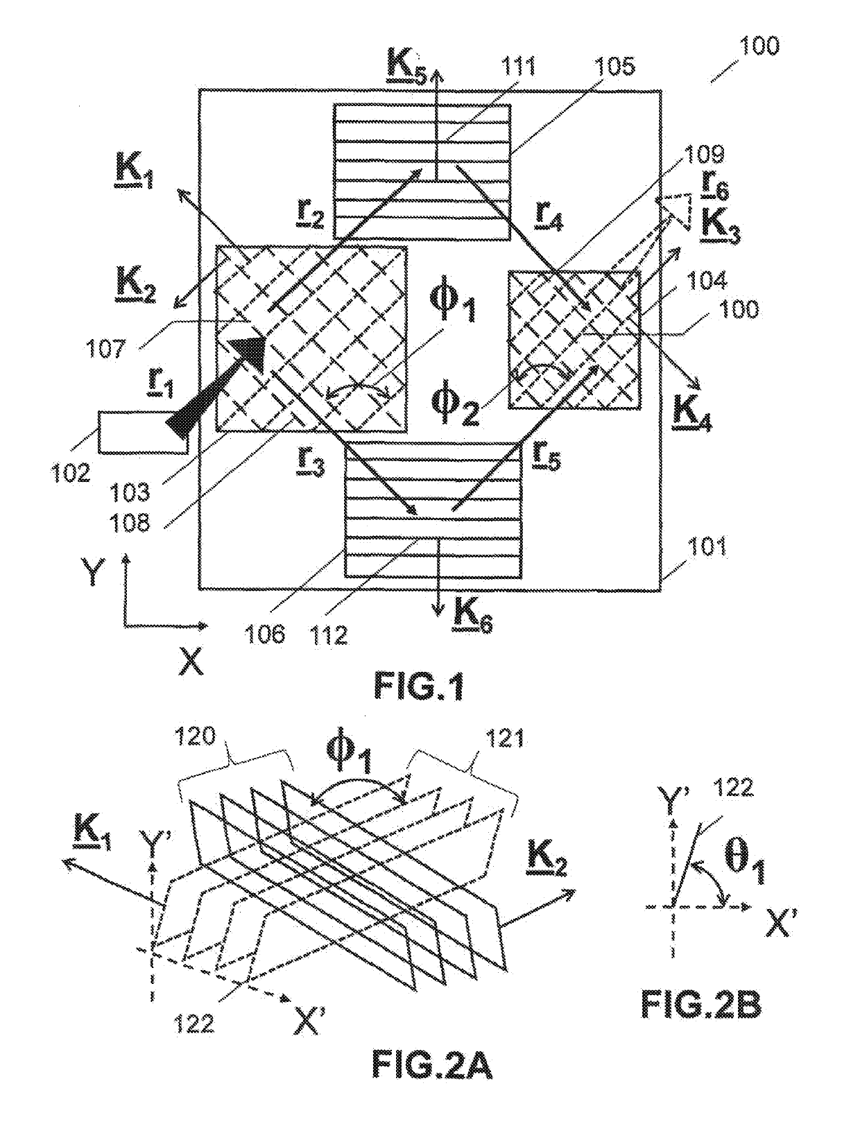
[0094]In some embodiments such as the one illustrated in FIGS. 13-14 the invention provides a means for propagating at least two beams of differing spectral bandwidth through the waveguide. FIG. 13 is a plan view of an embodiment 230 comprising a waveguide 230 of similar architecture to the one of FIG. 1 coupled to the light source 232. The input grating 233 and output grating 234 each combine crossed gratings with peak diffraction efficiency for orthogonal polarizations states, typically S-polarized and P-polarized. In FIG. 1 the input grating is formed from the crossed slant gratings 237,238 having grating vectors K21,K22, with the grating fringes being rotated in the waveguide plane (or clocked) at the relative angle and the output grating is formed from the crossed slant gratings 239,240 having grating vectors K23,K24, with the grating fringes being rotated in the waveguide plane (or clocked) at the relative angle ϕ4. The fold gratings 235,236 contain the slant gratings 241,242 ...

embodiment 250

[0095]In one embodiment 250 there is provided a waveguide for propagating light of more than one color, based on the embodiment of FIGS. 13-14, which includes a means for polarization recovery. As explained above by using crossed input gratings, we ensure that each input light polarization will be correctly aligned for diffraction by one of the crossed gratings. In a color waveguide application, we have at least two input polarizations and at least two colour components. Hence we require two crossed grating layers. The waveguide in the embodiment 250 comprises two bonded substrates, the lower one of which is essentially the waveguide 231 of FIGS. 13-14 and upper one 251 containing an input grating 252 overlaying the input grating of the lower substrate. The upper and lower input gratings sandwich a half wave retarder film 253. The input grating in the upper substrate is formed from the crossed slant gratings 253,254 having grating vectors K27, K28, with the grating fringes being rot...


PUM


Abstract

A waveguide apparatus, comprises: disposed in at least one layer: an input coupler; a first fold grating; a second fold grating; an output coupler; and a source of light optically coupled to the waveguide providing at least first and second polarizations of the light and at least one wavelength. The input coupler is configured to cause the first polarization light to travel along a first total internal reflection (TIR) path and the second polarization light to travel along a second TIR path.

Description

CROSS-REFERENCE TO PRIORITY APPLICATIONS[0001]This application is a U.S. national stage of PCT Application No. PCT / GB2017 / 000040 entitled METHOD AND APPARATUS FOR PROVIDING A POLARIZATION SELECTIVE HOLOGRAPHIC WAVEGUIDE DEVICE filed on Mar. 23, 2017, which claims the benefit of U.S. Provisional Application No. 62 / 390,271 entitled HOLOGRAPHIC WAVEGUIDE DEVICES FOR USE WITH UNPOLARIZED LIGHT filed on Mar. 24, 2016 and U.S. Provisional Application No. 62 / 391,333 entitled METHOD AND APPARATUS FOR PROVIDING A POLARIZATION SELECTIVE HOLOGRAPHIC WAVEGUIDE DEVICE filed on Apr. 21, 2016, the disclosures of which are hereby incorporated by reference in their entireties.BACKGROUND OF THE INVENTION[0002]The present disclosure relates to waveguide devices and more particularly to a holographic waveguide device for use with unpolarized light.[0003]Waveguide optics is currently being considered for a range of display and sensor applications for which the ability of waveguides to integrate multiple...

Claims


Application Information

Patent Timeline
Patent Type & Authority Applications(United States)
IPC IPC(8): G02B6/27G02B6/34G02B27/28G02B30/25
CPCG02B6/2726G02B6/2773G02B6/34G02B27/286G02B27/283G02B27/0081G02B27/017
Inventor POPOVICH, MILAN MOMCILOWALDERN, JONATHAN DAVIDGRANT, ALASTAIR JOHN
Owner DIGILENS
Why Eureka
Try Eureka