Fuel cell system and control method of fuel cell system

a fuel cell and control method technology, applied in the direction of fuel cell control, fuel cells, motive system fuel cells, etc., can solve the problems of deteriorating fuel economy and reducing compressor efficiency of the fuel cell system, and achieve the effect of preventing the pressure inside the fuel cell from rapidly decreasing, and reducing the cost of fuel cell installation

Active Publication Date: 2019-04-25
TOYOTA JIDOSHA KK
View PDF2 Cites 1 Cited by
  • Summary
  • Abstract
  • Description
  • Claims
  • Application Information

AI Technical Summary

Benefits of technology

[0010](5) The fuel cell system according to the aspect described above may further include a pressure regulating valve disposed on an upstream side of the turbine in the air discharge flow path and on a downstream side of a connection portion between the bypass flow path and the air discharge flow path and configured to regulate a pressure of the air flowing through the fuel cell. With this fuel cell system, it is possible to suppress abrupt fluctuation of the pressure on the upstream side of the pressure regulating valve. Thus, it is possible to prevent the pressure inside the fuel cell from rapidly decreasing along with, for example, the opening and closing of the bypass valve.
[0011](6) In the fuel cell system according to the aspect described above, a valve box of the pressure regulating valve may be formed integrally with a turbine housing of the turbine, and a valve body of the pressure regulating valve may be disposed on an upstream side of a turbine wheel in the turbine. With this fuel cell system, by adjusting the opening degree of the pressure regulating valve, it is possible to change the flow velocity of the air blown to the turbine wheel. Therefore, the configuration of the fuel cell system can be simplified, and the driving force by the turbine for assisting the driving of the compressor by the motor can be increased.
[0012](7) In the fuel cell system according to the aspect described above, the bypass flow path may be connected to an inside of a turbine housing of the turbine, a valve box of the bypass valve may be formed integrally with the turbine housing, and a valve body of the bypass valve may be disposed on an upstream side of a turbine wheel in the turbine. With this fuel cell system, it is possible to simplify the configuration of the fuel

Problems solved by technology

Thus, there is a possibility that efficiency of the compressor d

Method used


Image

  • Fuel cell system and control method of fuel cell system
  • Fuel cell system and control method of fuel cell system
  • Fuel cell system and control method of fuel cell system

Examples


first embodiment

A. First Embodiment

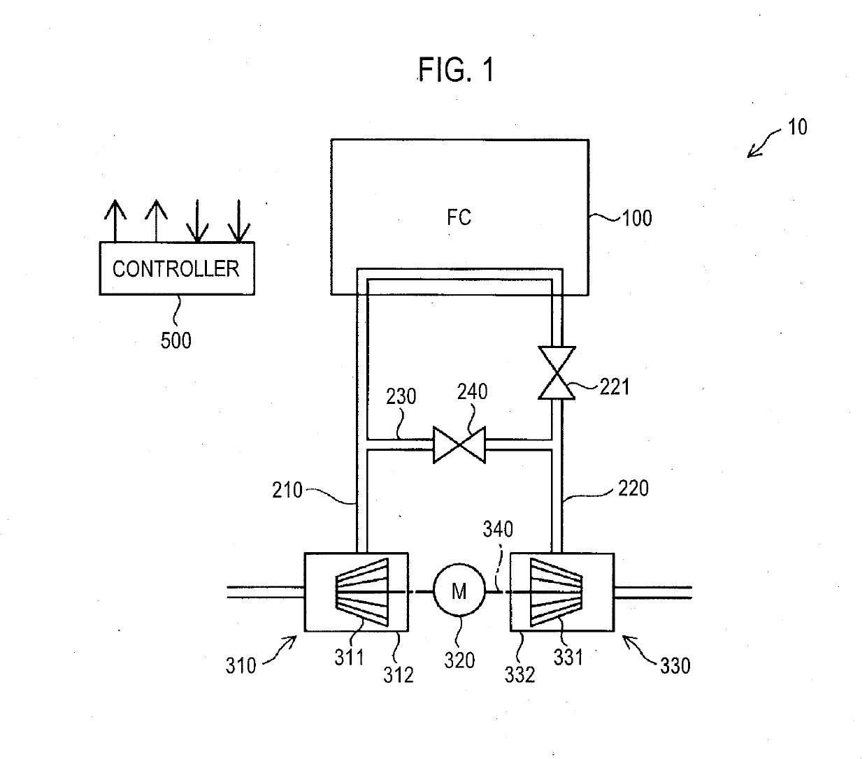
[0031]FIG. 1 is an explanatory diagram showing an outline of a fuel cell system 10 according to a first embodiment. The fuel cell system 10 according to the present embodiment is mounted on, for example, a fuel cell vehicle and is used as a power generation device for driving a drive motor of the fuel cell vehicle. The fuel cell system 10 may be used as a stationary power generation device. The fuel cell system 10 includes a fuel cell 100, an air supply flow path 210, an air discharge flow path 220, a bypass flow path 230, a bypass valve 240, a compressor 310, a motor 320, a turbine 330, and a controller 500. Hereinafter, “upstream side” and “downstream side” in the specification refer to an upstream side and a downstream side in a flow direction of air, respectively.

[0032]The fuel cell 100 of the present embodiment is a solid polymer type fuel cell. The fuel cell 100 has a stack structure in which a plurality of cells is stacked. Each cell includes a membrane ele...

second embodiment

B. Second Embodiment

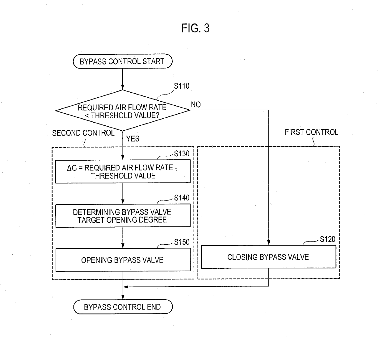
[0060]FIG. 6 is a flowchart showing contents of a bypass determination process according to a second embodiment. This process is a process for determining whether or not to execute the bypass control process shown in FIG. 3. This process is started when the power generation of the fuel cell 100 is started, and continues to circulate until the power generation of the fuel cell 100 stops. In the second embodiment, the configuration of the fuel cell system 10 is the same as that of the first embodiment (FIG. 1).

[0061]In the fuel cell system 10 of the second embodiment, the controller 500 acquires a required air flow rate G1 at time t1 that is Δt second (e.g., one second) before time t2 that is a current time (step S210), and then acquires a required air flow rate G2 at time t2 (step S220). Next, the controller 500 obtains an increase amount of the required air flow rate per unit time using the required air flow rate G1 at time t1 and the required air flow rate G2 at...

third embodiment

C. Third Embodiment

[0063]FIG. 7 is an explanatory diagram showing an outline of a fuel cell system 10c according to a third embodiment. The fuel cell system 10c of the third embodiment differs from the fuel cell system 10 of the first embodiment (FIG. 1) in that the fuel cell system 10c includes an accumulator tank 410, a tank pressure sensor 411, a first tank valve 420, and a second tank valve 430. Further, in the third embodiment, conditions for executing the bypass control are different from those of the first embodiment (FIG. 3).

[0064]The accumulator tank 410 is connected to a downstream side of the bypass valve 240 in the bypass flow path 230. The accumulator tank 410 is a tank for storing the air flowing through the bypass flow path 230.

[0065]The tank pressure sensor 411 is a pressure sensor for acquiring a pressure of the air stored in the accumulator tank 410.

[0066]The first tank valve 420 is disposed at a connecting portion between the accumulator tank 410 and the bypass fl...


PUM


Abstract

A fuel cell system includes a motor driving a compressor that supplies air to a fuel cell, a turbine assisting the compressor, a bypass valve that opens and closes the bypass flow path, and a controller. When a required air flow rate is equal to or higher than a threshold value, the controller closes the bypass valve and controls the motor to cause the air to flow through the fuel cell at a flow rate corresponding to the required air flow rate. When the required air flow rate is lower than the threshold value, the controller opens the bypass valve to cause the air to flow through the bypass flow path and controls the motor to cause the air to flow through the fuel cell at the flow rate corresponding to the required air flow rate.

Description

INCORPORATION BY REFERENCE[0001]The disclosure of Japanese Patent Application No. 2017-203170 filed on Oct. 20, 2017 including the specification, drawings and abstract is incorporated herein by reference in its entirety.BACKGROUND1. Technical Field[0002]The disclosure relates to a fuel cell system and a control method of the fuel cell system.2. Description of Related Art[0003]Regarding a fuel cell system, Japanese Unexamined Patent Application Publication No. 2013-182781 (JP 2013-182781 A), for example, discloses an air supply rotating machine that is driven by a drive motor and an expander rotating by energy of a cathode off-gas to supply air to a cathode of a fuel cell.SUMMARY[0004]In the fuel cell system described in JP 2013-182781 A, a flow rate of air required by a fuel cell is small in an operation state in which a required output power of the fuel cell is small. Therefore, a flow rate of air discharged by the air supply rotating machine (compressor) decreases. In this case, a...

Claims


Application Information

Patent Timeline
IPC IPC(8): H01M8/04746H01M8/0438H01M8/04111
CPCH01M8/04753H01M8/04395H01M8/04111H01M2250/20Y02E60/50H01M8/04776H01M8/04225H01M8/04H01M8/04298
Inventor SADAMITSU, TAKAHIRO
Owner TOYOTA JIDOSHA KK
Why Eureka
Try Eureka