System and Method for a Reciprocating Injection Pump

a reciprocating injection pump and system technology, applied in the field of system and method for pumping, can solve the problems of expensive down time for repair and replacemen

Inactive Publication Date: 2019-05-02
PREDOMINANT PUMPS & AUTOMATION SOLUTIONS LLC
View PDF6 Cites 119 Cited by
  • Summary
  • Abstract
  • Description
  • Claims
  • Application Information

AI Technical Summary

Problems solved by technology

Oil field pumps wear out and leak causing expensive down time for repair and replacement during oil production.

Method used


Image

  • System and Method for a Reciprocating Injection Pump
  • System and Method for a Reciprocating Injection Pump
  • System and Method for a Reciprocating Injection Pump

Examples


Embodiment Construction

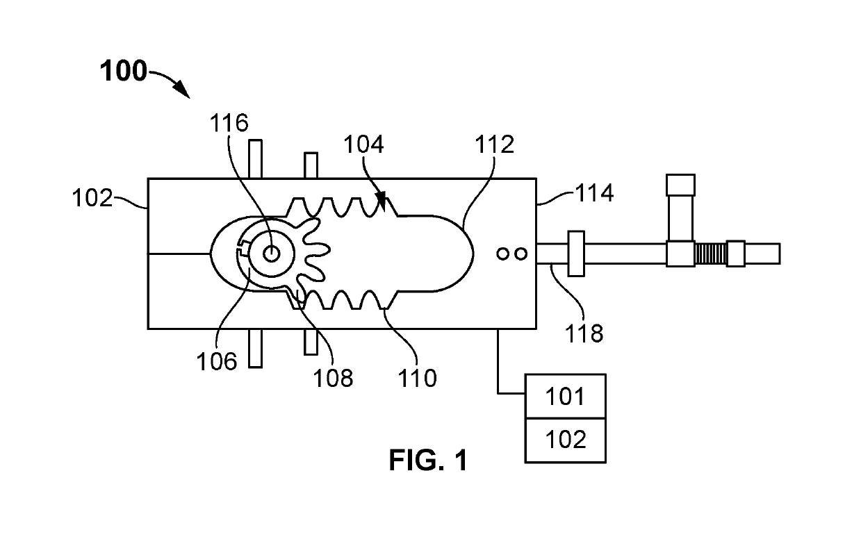
[0021]Turning now to FIG. 1, FIG. 1 is a plan view of an illustrative embodiment of the invention. As schematically depicted shown in FIG. 1, a reciprocating block 100 having a left end 102 and a right end 114 is driven back and forth, right and left by a rotating gear 106. The rotating gear has a substantially circular shape with four gear teeth 108 formed on the rotating gear along approximately one fourth of the circumference of the substantially circular shape of the rotating gear. The rotating gear 106 is attached to a rotating motor 117 (shown in FIG. 4) having a right-angle motor shaft 116. The motor shaft 116 is connected to the right-angle motor a minimal distance minimizing the length of the motor shaft to reduce torque losses associated with longer shaft lengths.

[0022]As shown in FIG. 4, the rotating gear 106 is mounted on the motor shaft 116 adjacent the motor 117 from the entry point of the shaft 116 to the motor 117 to reduce torque loss incurred that would occur if th...


PUM


Abstract

A reciprocating injection pump is disclosed including but not limited to a reciprocating block driven by a rotating gear, the gear having a substantially circular shape with four gear teeth formed on the rotating gear along approximately one fourth of the substantially circular shape, the rotating gear is attached to a rotating motor, the rotating motor having a right-angle motor shaft.

Description

CROSS REFERENCE TO RELATED PATENT APPLICATIONS[0001]This patent application claims priority from U.S. Provisional Patent Application Ser. No. 62 / 555,016 filed on 6 Sep. 2017 by Seth A Douglas entitled A System and Method for a Reciprocating Injection Pump which is hereby incorporated by reference herein in its entirety; and this patent application also claims priority from U.S. Provisional Patent Application Ser. No. 62 / 531,740 filed on 12 Jul. 2017 by Seth A Douglas entitled A System and Method for a Reciprocating Injection Pump which is also hereby incorporated by reference herein in its entirety.BACKGROUND OF THE INVENTION[0002]Oil field pumps wear out and leak causing expensive down time for repair and replacement during oil production.Field of the Invention[0003]A system and method for pumping that reduces expensive down time for repair and replacement during oil field production.BRIEF DESCRIPTION OF THE DRAWINGS[0004]FIG. 1, is a plan view of an illustrative embodiment of the ...

Claims


Application Information

Patent Timeline
Patent Type & Authority Applications(United States)
IPC IPC(8): F04B19/04F04B19/02F04B23/06F04B35/04F04B39/08E21B33/068F16H19/04
CPCF04B19/04F04B19/022F04B23/06F04B35/04F04B39/08E21B33/068F16H19/043F04B2203/02F04B9/02F04B17/03F04B49/065F16H19/04F04B1/053
Inventor DOUGLAS, III, SETH A.
Owner PREDOMINANT PUMPS & AUTOMATION SOLUTIONS LLC
Why Eureka
Try Eureka