Low-loss, low-profile digital-analog phase shifter

Active Publication Date: 2019-05-02
HUGHES NETWORK SYST
View PDF0 Cites 2 Cited by
  • Summary
  • Abstract
  • Description
  • Claims
  • Application Information

AI Technical Summary

Benefits of technology

This patent describes an apparatus and method for providing continuous phase shifts to an input signal, such as a radio frequency signal. The apparatus includes a digital shifter for performing coarse phase shifts and an analog shifter for variably shifting the phase of the input signal within a predetermined range. The result is a phase shifted RF signal with a total phase range of 0 to 360 degrees. The method involves receiving an input RF signal, performing coarse phase shifts and selectively using the analog shifters to produce the phase shifted RF signal. The technical effects of this patent include the ability to continuously vary the phase of an RF signal and improve the accuracy and reliability of phase shifting.

Problems solved by technology

The resolution is limited because number states are discrete.
In complex antenna configurations that require tens of thousands of digital shifters, the power requirements can result in heating and thermal interference problems.
Digital shifters also have an insertion loss that increases with the number of bits and with frequency increases.
Such losses can be intolerable for efficiency sensitive systems.
There are several drawbacks associated with analog shifters.
This results in limited range of phases that can be covered (up to about 100°).
Thus, sufficient phase shifts cannot be provided to cover the full 360° range without excessive signal loss.

Method used


Image

  • Low-loss, low-profile digital-analog phase shifter
  • Low-loss, low-profile digital-analog phase shifter
  • Low-loss, low-profile digital-analog phase shifter

Examples


Embodiment Construction

[0026]An apparatus and method are disclosed for providing continuous phase shifts to an input signal. In the following description, for purposes of explanation, numerous specific details are set forth in order to provide a thorough understanding of the disclosed embodiments. It will become apparent, however, to one skilled in the art that various embodiments may be practiced without these specific details or with an equivalent arrangement. In other instances, well-known structures and devices are shown in block diagram form in order to avoid unnecessarily obscuring the various embodiments.

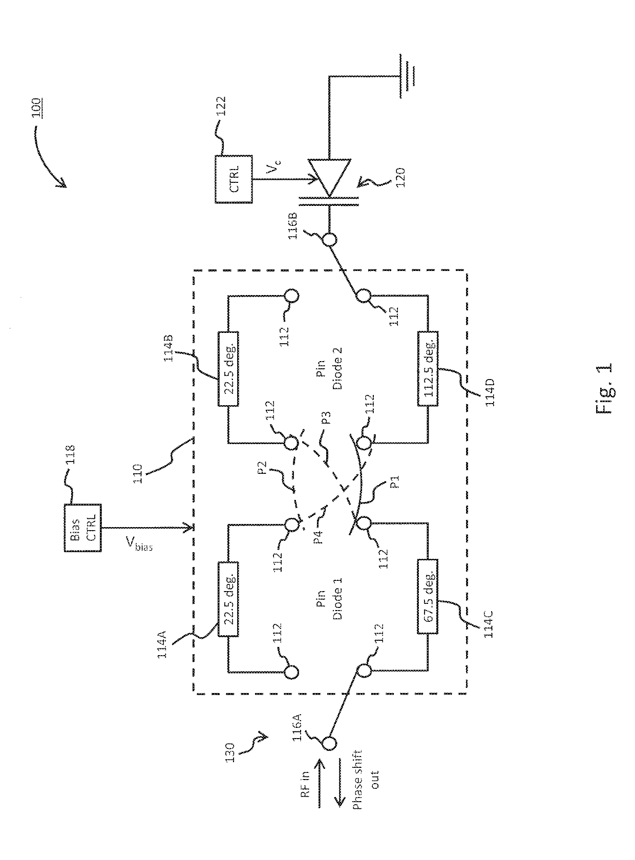
[0027]FIG. 1 is a diagram of a digital-analog phase shifter 100 in accordance with at least one embodiment. The digital-analog phase shifter 100 includes a digital shifter 110, an analog shifter 120, and an input / output port 130. According to the illustrated embodiment, the digital shifter 110 includes a plurality of switching elements 112, as well as four phase delay loads 114. Depending on the pa...


PUM


Abstract

A phase shifter having both digital and analog shifting components is disclosed. The digital-analog phase shifter includes an input / output port configured, in part, for receiving an input radio frequency (RF) signal from an external source and outputting a phase shifted RF signal. A digital shifter performs coarse phase shifts of the input RF signal, while an analog shifter variably shift the phase of the input RF signal relative to the coarse phase shift. This produces a phase shifted RF signal having a total phase range that is output is continuously variable from 0° to 360°.

Description

BACKGROUND INFORMATION[0001]Phase shifting circuits, or phase shifters, are utilized in a variety of applications and devices to shift the phase of an input signal. For example, the input signal can be a radio frequency (RF) signal or microwave signal that is utilized in a radar system, antenna array, etc. Depending on the specific system and level of complexity, the number of individual phase shifters can exceed tens of thousands.[0002]Phase shifters can be implemented as digital or analog components. Digital phase shifters (or digital shifters) often utilize pin diodes to select between a limited number of discrete phase shifts that can be applied to the input signal. A pin diodes can be switched on and off by changing its resistance from around 100 kΩ to less than 1Ω. This can be achieved, for example, by altering voltage bias of a pin diode from forward bias to reverse bias direction, or vice versa. The number of discrete phase shifts are often described in terms of an exponenti...

Claims


Application Information

Patent Timeline
IPC IPC(8): H01P1/185H03K17/74
CPCH01P1/185H03K17/74H03H7/185H03H7/20
Inventor LU, BINGQIANALSAWAHA, HAMADHOU, PETERJACKSON, THOMASMAO, YILIN
Owner HUGHES NETWORK SYST
Why Eureka
Try Eureka