Speed reducing device having power source

a technology of speed reducing device and power source, which is applied in the direction of gearing details, gearing, transportation and packaging, etc., can solve the problems of inconvenient application of connection structure to industrial robotic arm or power assisting device, and the inability to drive a large-sized load, etc., to achieve the effect of reducing the weight and volume of the speed reducing devi

Active Publication Date: 2019-05-09
DELTA ELECTRONICS INC
View PDF0 Cites 0 Cited by
  • Summary
  • Abstract
  • Description
  • Claims
  • Application Information

AI Technical Summary

Benefits of technology

[0007]An object of the present disclosure provides a speed reducing device comprising a motor and a speed reducing mechanism. The motor and the speed reducing mechanism are combined together without the use of a connection structure (e.g., a shaft coupling or a gear box). Since the motor and the speed reducing mechanism are combined as an integral structure, the weight and volume of the speed reducing device are reduced.

Problems solved by technology

In other words, it is difficult to drive a large-sized load.
In other words, the connection structure for connecting the reducer and the motor cannot be applied to the device that requires light weight and compact space.
For example, the connection structure is not suitably applied to an industrial robotic arm or a power assisting device.
However, since this reducer uses a mono-cycloidal set (i.e., a single cycloid), some drawbacks occur.
For example, when the reducer is operated at a high speed, it is difficult to maintain the dynamic balance state.
Consequently, the operation of the reducer results in high vibration.

Method used


Image

  • Speed reducing device having power source
  • Speed reducing device having power source
  • Speed reducing device having power source

Examples


Embodiment Construction

[0017]The present disclosure will now be described more specifically with reference to the following embodiments. It is to be noted that the following descriptions of preferred embodiments of this disclosure are presented herein for purpose of illustration and description only. It is not intended to be exhaustive or to be limited to the precise form disclosed.

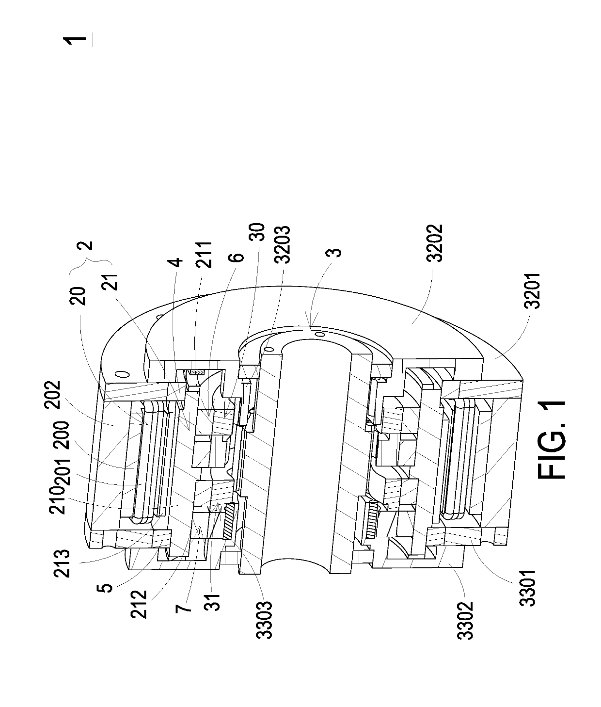
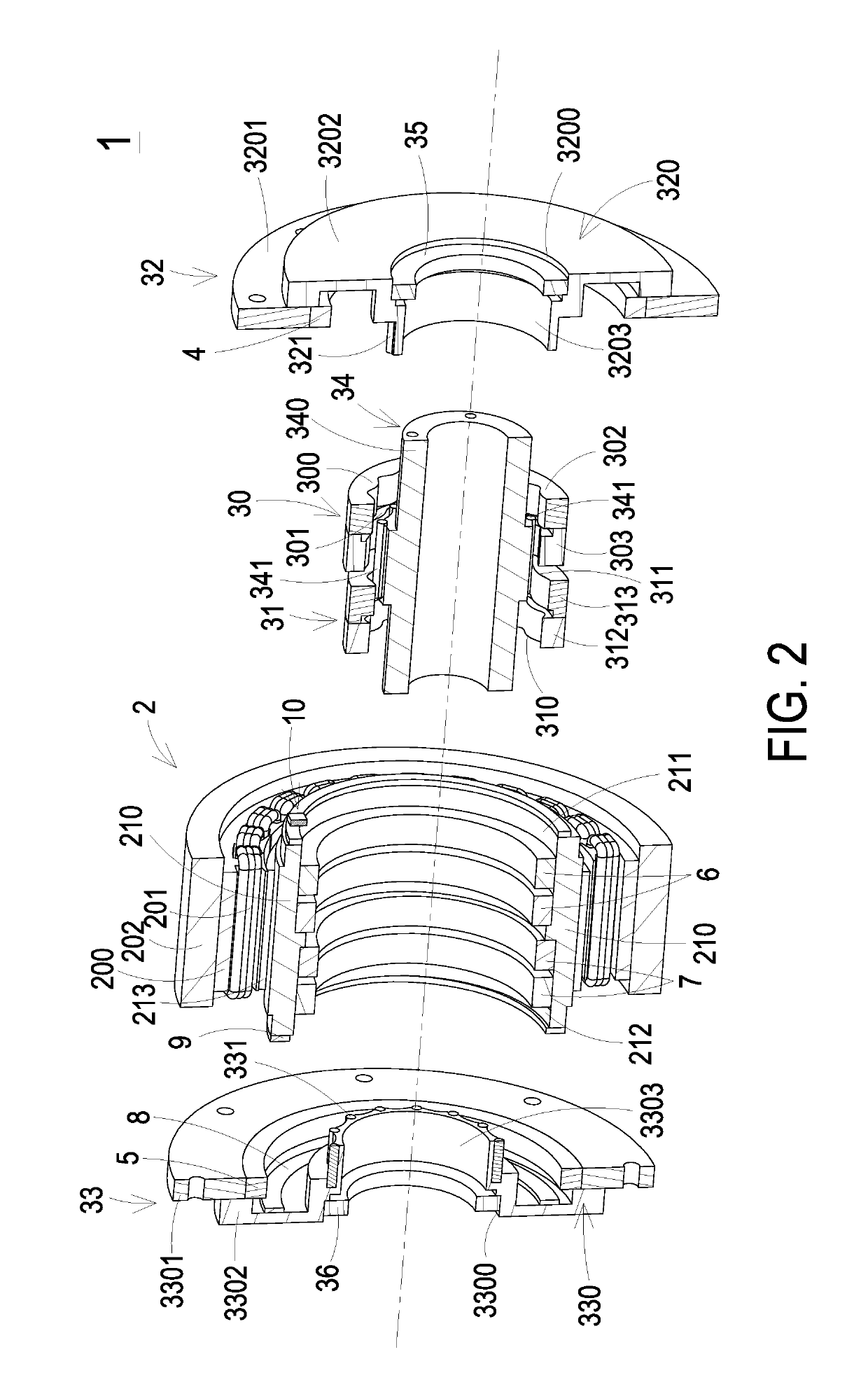
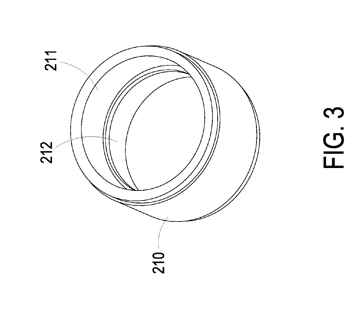
[0018]Please refer to FIGS. 1, 2 and 3. FIG. 1 is a schematic cutaway view illustrating a speed reducing device having a power source according to a first embodiment of the present disclosure. FIG. 2 is a schematic exploded view illustrating the speed reducing device of FIG. 1. FIG. 3 is a schematic perspective view illustrating a rotor portion of a motor of the speed reducing device of FIG. 1. The speed reducing device having a power source (hereinafter referred to as the speed reducing device 1) can be applied to various power mechanical devices such as industrial robotic arms or power assisting devices in order to provide a ...


PUM


Abstract

A speed reducing device includes a motor and a speed reducing mechanism. The motor includes a stator portion and a rotor portion. The rotor portion includes a first eccentric ring and a second eccentric ring. The speed reducing mechanism is partially accommodated within the rotor portion. The speed reducing mechanism includes a first roller assembly, a second roller assembly, a third roller assembly, a first cycloid disc set and a second cycloid disc set. The first roller assembly includes at least one first roller. The second roller assembly includes at least one second roller. The third roller assembly includes an output shaft and at least one third roller. The first cycloid disc set is mounted around the output shaft and disposed within the first eccentric ring. The second cycloid disc set is mounted around the output shaft and disposed within the second eccentric ring.

Description

CROSS-REFERENCE TO RELATED APPLICATION[0001]This application claims the benefit of U.S. Provisional Application No. 62 / 581,345 filed on Nov. 3, 2017, and entitled “POWER GEAR”, the entirety of which is hereby incorporated by reference.FIELD OF THE INVENTION[0002]The present disclosure relates to a speed reducing device, and more particularly to a speed reducing device having a power source.BACKGROUND OF THE INVENTION[0003]Generally, a motor is operated at a high speed and a low torsion force. In other words, it is difficult to drive a large-sized load. Consequently, for allowing the motor to drive a heavy object, a reducer is used for reducing the rotating speed of the motor and increasing the torsion force.[0004]Conventionally, the reducer and the motor are separate components. It is necessary to connect the reducer with the motor through an additional connection structure such as a shaft coupling or a gear box. In such way, the volume and weight of the overall structure of the red...

Claims


Application Information

Patent Timeline
Patent Type & Authority Applications(United States)
IPC IPC(8): H02K7/116B60K17/346
CPCH02K7/116B60K17/3467F16H1/32F16H57/023
Inventor TSAI, CHING-HSIUNGCHUNG, CHI-WENCHU, EN-YI
Owner DELTA ELECTRONICS INC
Why Eureka
Try Eureka