Catheter tension sensing

Active Publication Date: 2019-05-16
AURIS HEALTH INC
View PDF0 Cites 35 Cited by
  • Summary
  • Abstract
  • Description
  • Claims
  • Application Information

AI Technical Summary

Benefits of technology

The patent describes a robotic surgical system that has a control system and an instrument driver. The control system receives information to position a catheter and the instrument driver has a rotary output motor to move the catheter. The system measures the torque of the output shaft by using a sensor. The technical effect of this invention is to provide a reliable and accurate way to measure the force applied by a robotic surgical system to a patient's body.

Problems solved by technology

However, at times the calculated motion of the catheter does not precisely match the actual motion within the patient's anatomy.
Various elements can affect the amount of articulation for a given pullwire actuation, including the presence of unanticipated or un-modeled constraints imposed by the patient's anatomy, particularly given the tortuous path that the catheter must traverse.
Additionally, while the position of the output shaft is calculated, the torque applied at the output shaft cannot be precisely calculated because of the variations in transmission efficiency and the effects of perturbations on the system due to catheter construction shape and use.
Moreover, external forces on the catheter can change the loading on the catheter pullwires and, for a fixed position of the output shaft, in turn may change the torsion loading on the output shafts.
However, differences between predicted and actual catheter position can result from the reliance by the kinematic model on certain assumptions and the lack of certain information.
Even with rigid structures, external forces, even gravity, may disrupt the ability to solve the location equation given the information above.
However, when a load is placed on the beam, the distal end will deflect, or strain under the load.
Even in a purely elastic response to the load, the location or orientation of the distal end of the beam is impossible to predict without knowing the magnitude, the direction, and the location of the external load.
However, in reality, the drivetrain is not perfectly rigid.
One difficulty that may be experienced with this technique, i.e., where the motor 604 is oriented parallel to the output shaft 600, is that in addition to the output shaft torque, the sensor 602 would also pick up inertial forces from the acceleration and deceleration of the motor 604.
One of the challenges with measuring the torque in the output shaft directly is that the output shaft 600 must be free to rotate, potentially numerous complete revolutions.
This requirement can make routing the necessary signal connections (electrical, fiber optic, etc.) to the sensing element challenging.
While implementing a force sensing element in a splayer provides a direct measurement, it may generally increase the cost associated with disposable elements of the system.

Method used


Image

  • Catheter tension sensing
  • Catheter tension sensing
  • Catheter tension sensing

Examples


Embodiment Construction

[0031]Referring now to the discussion that follows and also to the drawings, illustrative approaches to the disclosed assemblies are shown in detail. Although the drawings represent some possible approaches, the drawings are not necessarily to scale and certain features may be exaggerated, removed, or partially sectioned to better illustrate and explain the present disclosure. Further, the descriptions set forth herein are not intended to be exhaustive or otherwise limit or restrict the claims to the precise forms and configurations shown in the drawings and disclosed in the following detailed description.

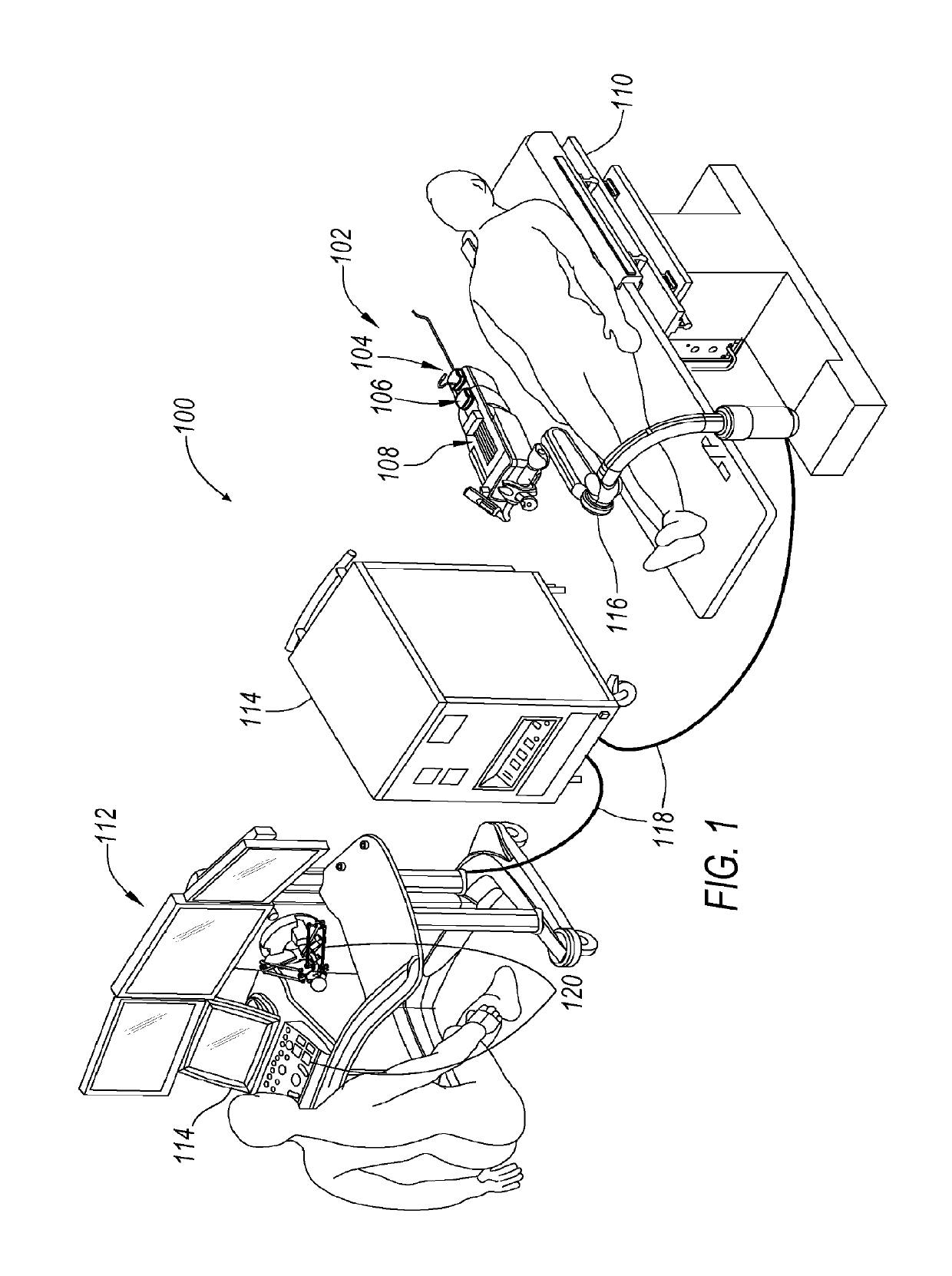
[0032]Referring to FIG. 1, a robotic surgical system 100 is illustrated in which an apparatus, a system, and / or method may be implemented according to various exemplary illustrations. System 100 may include a robotic catheter assembly 102 having a sheath instrument 104 and / or a catheter instrument 106. Catheter assembly 102 is controllable using a robotic instrument driver 108 (gen...


PUM


Abstract

This disclosure covers various concepts to use for obtaining measurement of tension in catheter pullwires to improve controllability of a robotic surgical system.

Description

CROSS REFERENCE TO RELATED APPLICATIONS[0001]This application is a continuation of U.S. patent application Ser. No. 15 / 357,537 filed Nov. 21, 2016, which is a continuation of U.S. patent application Ser. No. 14 / 214,711 filed Mar. 15, 2014, which is a continuation-in-part application of U.S. patent application Ser. No. 13 / 828,342 filed Mar. 14, 2013, and also claims priority to U.S. Provisional Patent Application No. 61 / 793,347 filed Mar. 15, 2013. The contents of each of the above applications are hereby incorporated by reference in their entirety for all purposes.TECHNICAL FIELD[0002]The present disclosure generally relates to robotic surgical system for performing minimally invasive diagnostic and therapeutic procedures and particularly to how to measure tension in catheter pullwires in a robotic catheter systems for steerable catheters.BACKGROUND[0003]Robotic surgical systems and devices are well suited for use in performing minimally invasive medical procedures, as opposed to co...

Claims


Application Information

Patent Timeline
IPC IPC(8): A61B34/00A61M25/01A61B34/30A61B90/00
CPCA61B34/71A61M25/0147A61B34/30A61B90/06A61B2017/00477A61M2025/0166A61B2034/715A61B2090/066A61M2025/015A61B2034/301
Inventor COVINGTON, TRAVIS
Owner AURIS HEALTH INC
Why Eureka
Try Eureka