Eureka AIR delivers breakthrough ideas for toughest innovation challenges, trusted by R&D personnel around the world.

Scintillator, method of forming the same, and radiation detection apparatus

Active Publication Date: 2019-05-16
CANON KK
View PDF7 Cites 3 Cited by
  • Summary
  • Abstract
  • Description
  • Claims
  • Application Information

AI Technical Summary

Benefits of technology

The invention offers a method that can prevent bright burn while also improving the quality of a scintillator.

Problems solved by technology

However, such a composition will cause a deterioration in the crystallinity of the scintillator or a reduction in the transmission efficiency of light in the scintillator.

Method used


Image

  • Scintillator, method of forming the same, and radiation detection  apparatus
  • Scintillator, method of forming the same, and radiation detection  apparatus
  • Scintillator, method of forming the same, and radiation detection  apparatus

Examples


Embodiment Construction

[0011]The preferred embodiments of the present invention will be described below with reference to the accompanying drawings. Note that the respective drawings are merely illustrated for the purpose of describing structures or configurations, and the dimensions of the illustrated respective members do not necessarily reflect actual dimensions. In addition, the same reference numerals denote the same elements in the respective drawings, and a repetitive description will be omitted.

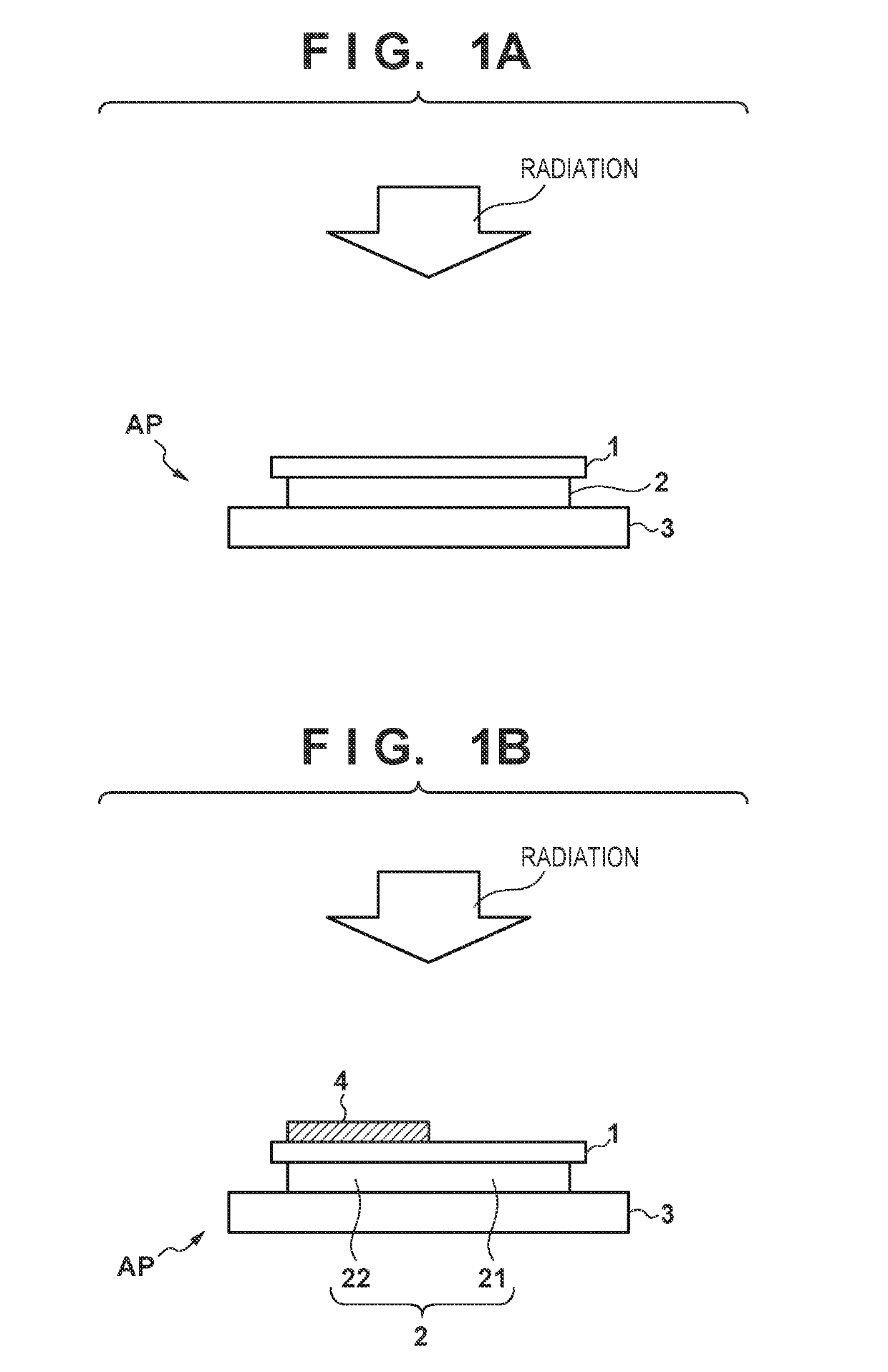
[0012]FIGS. 1A and 1B are schematic views for explaining a method of evaluating bright burn. As shown in FIG. 1A, bright burn is evaluated with respect to a radiation detection apparatus AP obtained by bonding a scintillator 2 vapor-deposited on a substrate 1 onto a sensor substrate (sensor unit) 3 on which a plurality of photoelectric conversion elements are arrayed. The scintillator 2 generates light (scintillation light) upon receiving radiation. The sensor substrate 3 detects this light. Assume that the...


PUM


Abstract

A scintillator having a columnar crystal structure vapor-deposited on a substrate, wherein each column of the crystal structure contains an alkali halide metal compound as a host material, and further contains, as an additive, a compound of a precious metal as a metal having lower ionization tendency than hydrogen (H), with the additive having a lower melting point than the host material.

Description

BACKGROUND OF THE INVENTIONField of the Invention[0001]The present invention relates to a scintillator, a method of forming the same, and a radiation detection apparatus.Description of the Related Art[0002]Some radiation detection apparatuses (or radiation imaging apparatuses) are configured to convert radiation into light using a scintillator and detect the light using photoelectric conversion elements. A scintillator sometimes varies in characteristics in accordance with irradiation with radiation. Such a phenomenon is also called “bright burn” (see Japanese Patent Laid-Open No. 2016-88988).[0003]Japanese Patent Laid-Open No. 2016-88988 discloses, as an example of a method of suppressing bright burn, a method of letting a scintillator include atoms as monovalent cations more than an activator agent for improving the luminous efficiency of the scintillator. However, such a composition will cause a deterioration in the crystallinity of the scintillator or a reduction in the transmis...

Claims


Application Information

Patent Timeline
IPC IPC(8): G01T1/202G01T1/20C09K11/58
CPCG01T1/2023G01T1/2018C09K11/58C09K11/616G21K4/00
Inventor OIKE, TOMOYUKISARUTA, SHOSHIRO
Owner CANON KK
Why Eureka
Eureka Blog
Learn More