Spin-orbit-torque magnetization rotational element, spin-orbit-torque magnetoresistance effect element, and magnetic memory
a spin-orbit torque and rotational element technology, applied in the direction of galvano-magnetic hall-effect devices, magnetic bodies, instruments, etc., can solve the problems of unstable magnetization of ferromagnetic substances, heat generation of spin-orbit torque wiring, and impurities, etc., to achieve easy writing current flow and easy magnetization
- Summary
- Abstract
- Description
- Claims
- Application Information
AI Technical Summary
Benefits of technology
Problems solved by technology
Method used
Image

Examples
first embodiment
[0034]Spin-Orbit-Torque Magnetization Rotational Element
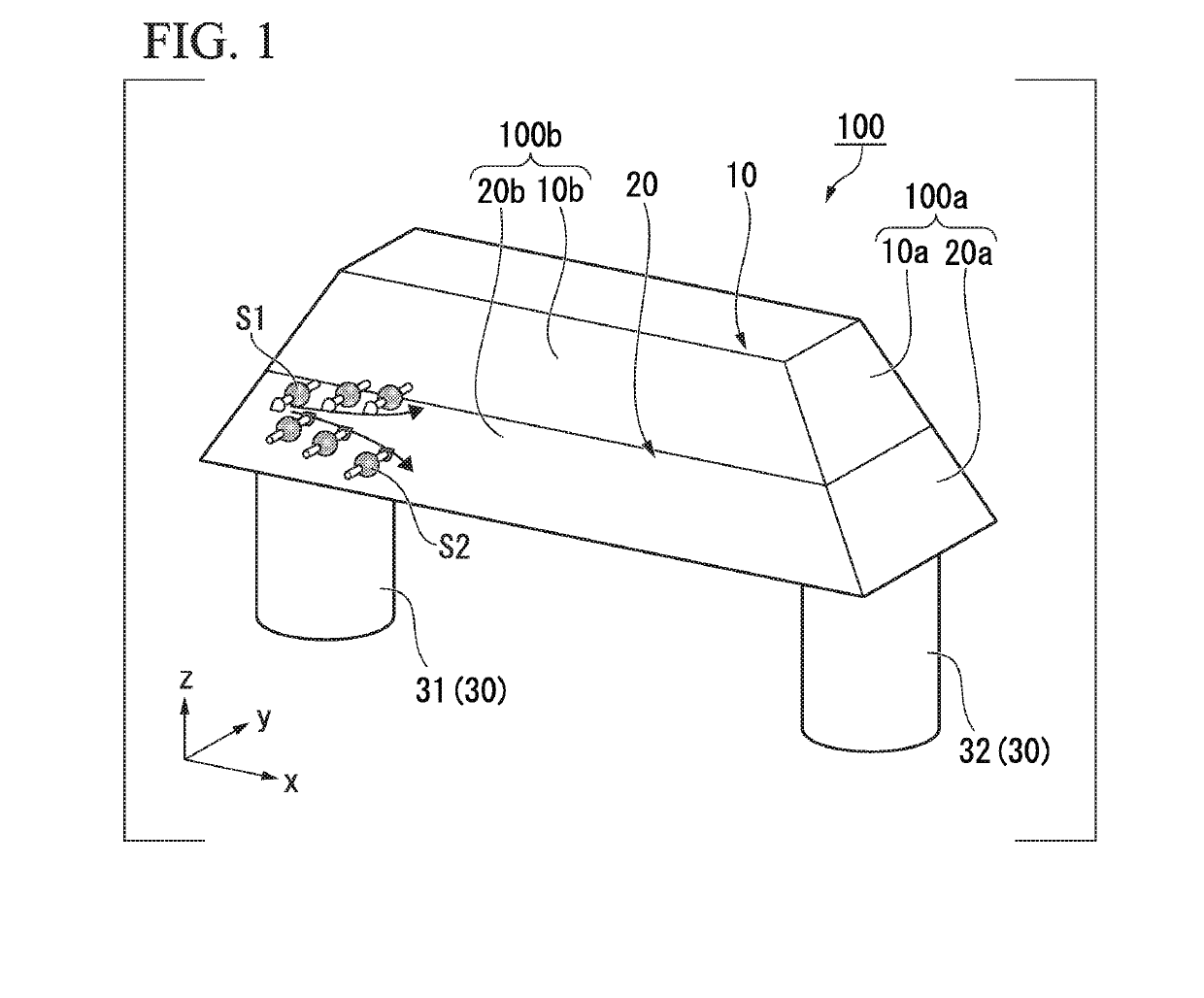
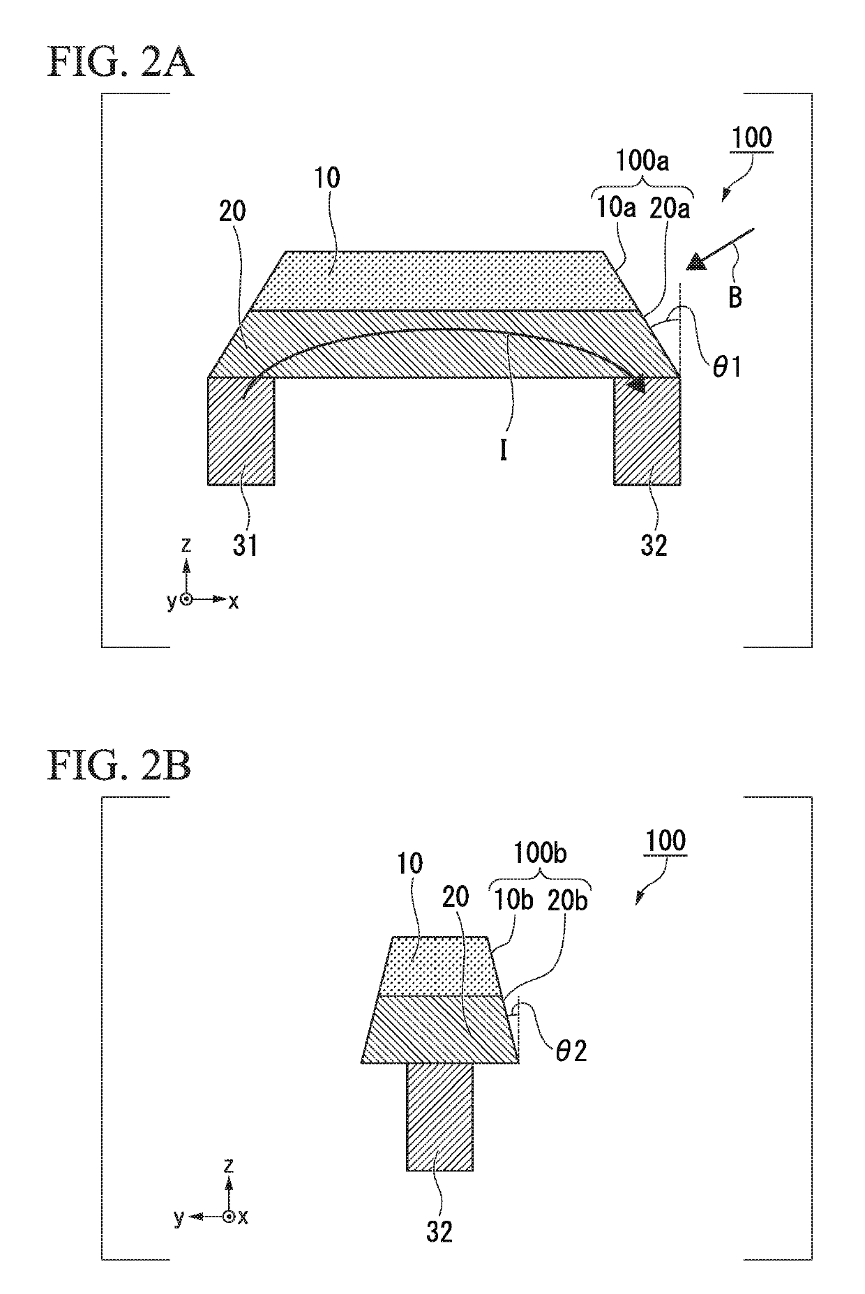
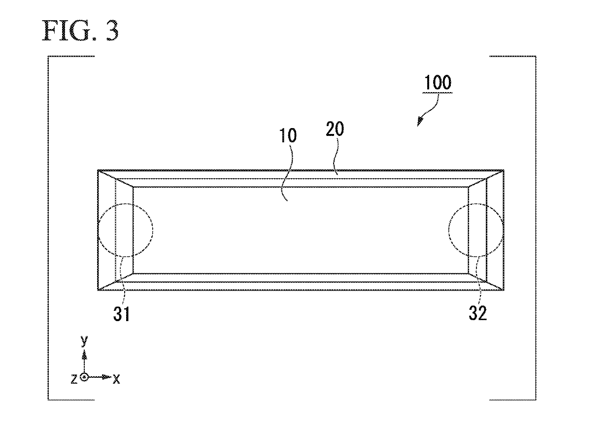
[0035]FIG. 1 is a perspective view schematically illustrating a spin-orbit-torque magnetization rotational element according to a first embodiment. In addition, FIGS. 2A and 2B are cross-sectional views schematically illustrating the spin-orbit-torque magnetization rotational element according to the first embodiment.
[0036]A spin-orbit-torque magnetization rotational element 100 according to the first embodiment includes a first ferromagnetic layer 10 and a spin-orbit torque wiring 20. In addition, the spin-orbit-torque magnetization rotational element 100 illustrated in FIG. 1 further includes two via wirings 30 (a first via wiring 31 and a second via wiring 32). Hereinafter, a first direction in which the spin-orbit torque wiring 20 extends is defined as an x direction, a second direction that intersects the x direction in a plane in which the spin-orbit torque wiring 20 extends is defined as a y direction, and a direction th...
second embodiment
[0096]Spin-Orbit-Torque Magnetoresistance Effect Element
[0097]FIGS. 7A and 7B are schematic cross-sectional views of a spin-orbit-torque magnetoresistance effect element according to a second embodiment. A spin-orbit-torque magnetoresistance effect element 200 illustrated in FIGS. 7A and 7B includes the spin-orbit-torque magnetization rotational element 103 illustrated in FIGS. 6A and 6B, a second ferromagnetic layer 60, and a nonmagnetic layer 70. The second ferromagnetic layer 60 is disposed to face a side of the first ferromagnetic layer 10 which is opposite to the spin-orbit torque wiring 20. The nonmagnetic layer 70 is interposed between the first ferromagnetic layer 10 and the second ferromagnetic layer 60. In addition, the spin-orbit-torque magnetization rotational element 103 is illustrative only, and the configurations illustrated in FIGS. 2A and 2B, and FIGS. 5A and 5B may be used.
[0098]A laminated body (functional part 80) in which the first ferromagnetic layer 10, the no...
third embodiment
[0107]Magnetic Memory
[0108]FIG. 8 is a plan view of a magnetic memory 300 including a plurality of the spin-orbit-torque magnetoresistance effect elements 200 (refer to FIGS. 7A and 7B). In the magnetic memory 300 illustrated in FIG. 8, the spin-orbit-torque magnetoresistance effect elements 200 are arranged in a matrix of 3×3. FIG. 8 is an example of a magnetic memory, and the number of the spire-orbit-torque magnetoresistance effect elements 200 and the arrangement thereof are arbitrary.
[0109]One of word lines WL1 to WL3, one of source lines SL1 to SL3, and one of read lines RL1 to RL3 are connected to each of the spin-orbit-torque magnetoresistance effect elements 200.
[0110]When the word lines LW1 to LW3, and the source lines SL1 to SL3 are selected to apply a current, the current is allowed to flow to the spin-orbit torque wiring 20 of arbitrary spin-orbit-torque magnetoresistance effect element 200, and a write operation is performed. In addition, when the read lines RL1 to RL3...
PUM
 Abstract
Description
Claims
Application Information
 - R&D Engineer
- R&D Manager
- IP Professional
- Industry Leading Data Capabilities
- Powerful AI technology
- Patent DNA Extraction
Browse by: Latest US Patents, China's latest patents, Technical Efficacy Thesaurus, Application Domain, Technology Topic.
© 2024 PatSnap. All rights reserved.Legal|Privacy policy|Modern Slavery Act Transparency Statement|Sitemap