Magnetic field sensor provided with an upper shield layer having portions with different magnetostriction

Inactive Publication Date: 2006-11-23
TDK CORPARATION
View PDF6 Cites 13 Cited by
  • Summary
  • Abstract
  • Description
  • Claims
  • Application Information

AI Technical Summary

Benefits of technology

[0010] The object of the present invention is to provide a magnetic field sensor which stabilizes the magnet

Problems solved by technology

However, actually, the shield layers are magnetized by the surroundings, and as a result, the free layer is affected by the shield layers.
Magnetization of the upper shield layer that is caused by these effects is unstable because it depends on the magnitude of the external magnetic field or the condition of heating in the coil.
As a result, the bias magnetic field is disturbed, resulting in difficulty in applying the desired bias magnetic field to the free layer and in achieving stable output characteristics.
However, the shield layer in a multi-layer structure which is described in the above patent document needs a complex fabrication process, and this causes an increase

Method used


Image

  • Magnetic field sensor provided with an upper shield layer having portions with different magnetostriction
  • Magnetic field sensor provided with an upper shield layer having portions with different magnetostriction
  • Magnetic field sensor provided with an upper shield layer having portions with different magnetostriction

Examples


first embodiment

The First Embodiment

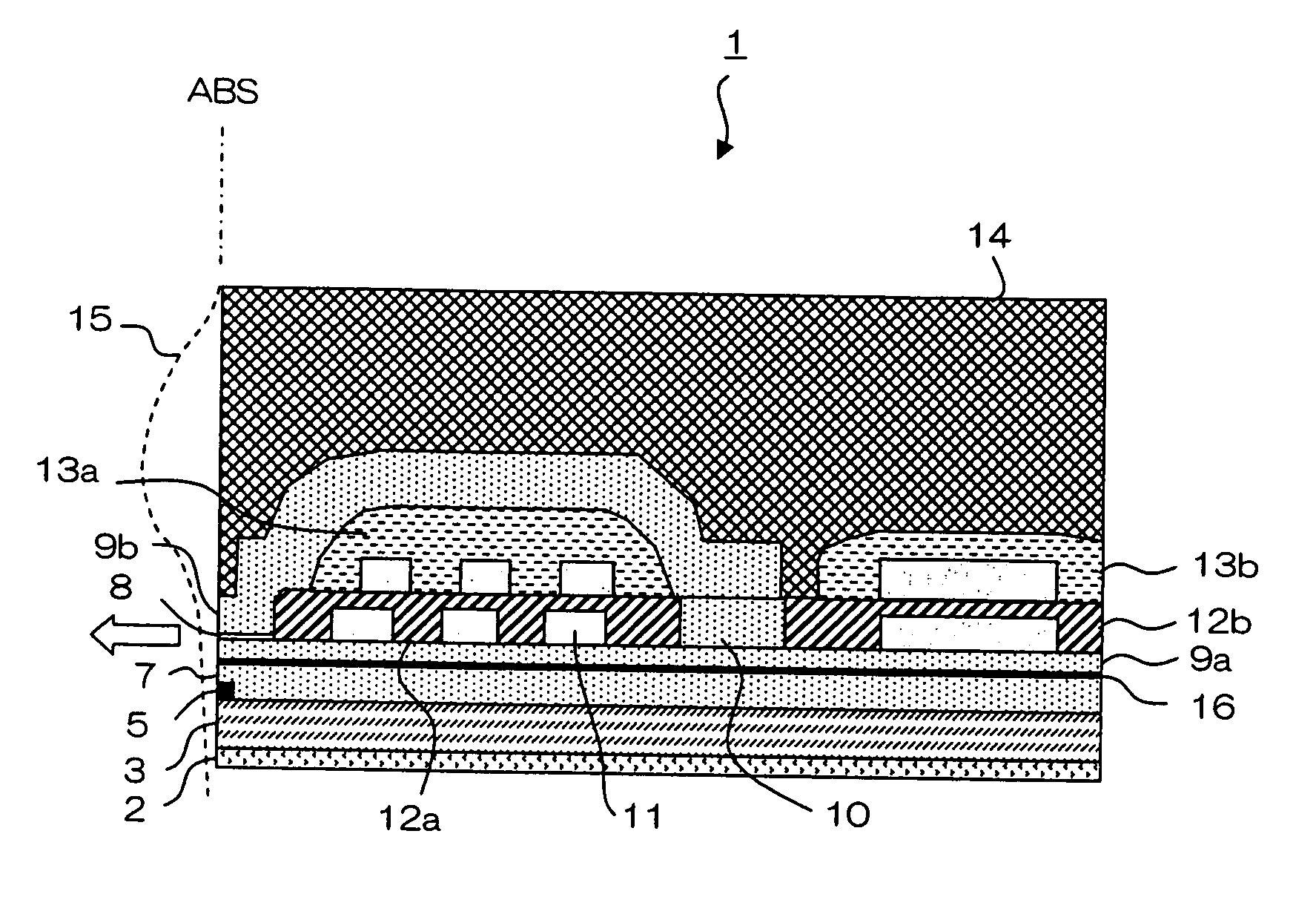
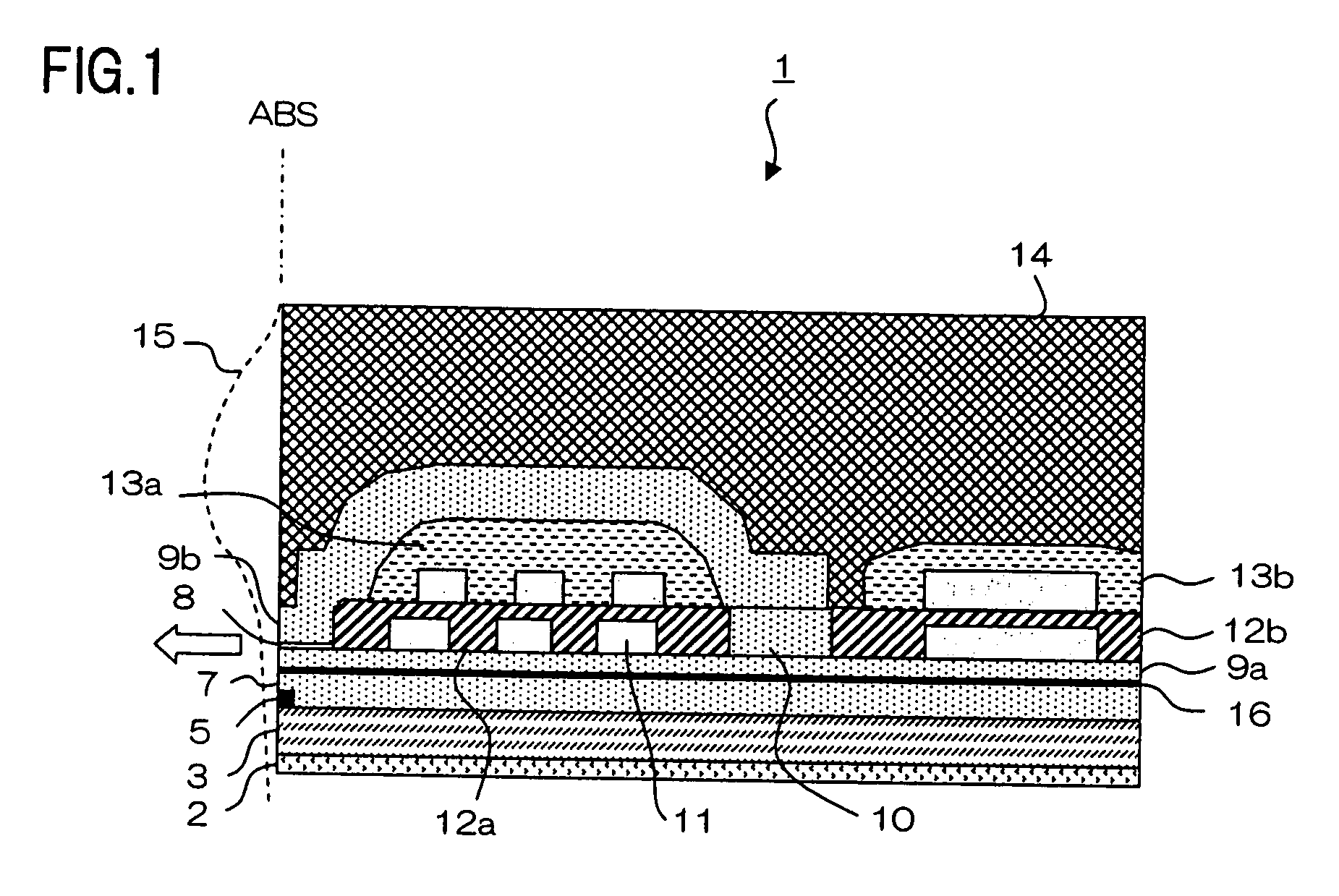
[0050] The first embodiment of a magnetic field sensor of the present invention will be described in detail with reference to the drawings. FIG. 1 is a partial sectional view of a thin-film magnetic head having a magnetic field sensor of the present invention. Thin-film magnetic head 1 has a substrate, not shown, that is made of ceramic, such as AlTiC (Al2O3.TiC), and layers beginning from seed layer 2 to protective layer 14 which are stacked in this order, as will be described later.

[0051] Specifically, lower shield layer 3 made of perm-alloy (NiFe) is formed on the substrate, with seed layer 2 made of alumina (Al2O3) interposed therebetween. Lower shield layer 3 functions as a lower magnetic shield layer for the reproducing head, or MR element 5 which functions as a magnetic field detecting element. MR element 5 is formed on lower shield layer 3 on the side of the air bearing surface (ABS), which is the surface of thin-film magnetic head 1 that faces a recordi...

second embodiment

The Second Embodiment

[0073] Next, the second embodiment of a thin-film magnetic head of the present invention will be described. Since this embodiment is the same as the first embodiment except for the configurations of the first portion and the lead electrodes, the description will focus on the configurations of the first portion and the lead electrodes.

[0074]FIG. 5A is a side view of a thin-film magnetic head, viewed from ABS. FIG. 5B is a partial plan view showing the location near the MR element and the lead electrodes. Upper shield layer 7d includes first portion 71d and second portion 72d. First portion 71d is formed such that it fills only recess 26d and extends in approximately the same cross section along the height direction. This configuration corresponds to the configuration of lead electrodes 24d in which the electrodes extend along the height direction with approximately the same spacing therebetween. Such a configuration in which the first portion 71d is elongate in ...

third embodiment

The Third Embodiment

[0075] Next, the third embodiment of a thin-film magnetic head of the present invention will be described. Since this embodiment is the same as the first embodiment except for the configurations of the first portion and the lead electrodes, the description will focus on the configurations of the first portion and the lead electrodes.

[0076]FIG. 6A is a side view of a thin-film magnetic head, viewed from ABS. FIG. 6B is a partial plan view showing the location near an MR element and lead electrodes. FIG. 6C is a sectional view taken along line C-C in FIG. 6B. A pair of lead electrodes 24e are provided on both sides of MR element 5 with respect to the track width direction. Upper gap layer 6e extends to cover the opposing surfaces of the pair of lead electrodes 24e, as well as MR element 5. As a result, recess 26e is formed between the opposing surfaces of upper gap layer 6e. Upper shield layer 7e has first portion 71e and second portion 72e. First portion 71e, dif...


PUM


Abstract

A magnetic field sensor comprises: a magnetic field detecting element that detects magnitude of an external magnetic field based on electric resistance of the magnetic field detecting element to sense current, the electric resistance being varied in accordance with the external magnetic field; an upper shield layer that is formed to cover the magnetic field detecting element; and a protective layer that is formed above the upper shield layer with respect to a direction of stacking. The upper shield layer includes a first portion at least part of which covers a top surface of the magnetic field detecting element, and a second portion that covers the first portion, and, the first portion has a larger absolute value of magnetostriction than the second portion.

Description

[0001] The present application is based on, and claims priority from, J.P. Application No. 2005-129413, filed on Apr. 27, 2005, the disclosure of which is hereby incorporated by reference herein in its entirety. BACKGROUND OF THE INVENTION [0002] 1. Field of the Invention [0003] The present invention relates to a magnetic field sensor, in particular to the structure of an upper shield layer of a magnetic field sensor that utilizes magneto-resistive effect. [0004] 2. Description of the Related Art [0005] Development of high density magnetic recording in hard disk drives has almost reached the 100 Gbpsi class on a mass production basis. In order to cope with the tendency toward high density magnetic recording, a magnetic field sensor that uses a magneto-resistive effect, such as a MR (Magneto-Resistive) element, has been used as a magnetic head. In particular, a GMR (Giant Magneto-Resistive) element using a spin valve (SV) film provides a highly sensitive magnetic head because of the ...

Claims


Application Information

Patent Timeline
IPC IPC(8): G11B5/33G11B5/127
CPCB82Y10/00G11B5/3909G11B2005/3996G11B5/3929G11B5/3912
Inventor HIRATA, KEIMACHITA, TAKAHIKOSHIMAZAWA, KOJINOGUCHI, KIYOSHI
Owner TDK CORPARATION
Why Eureka
Try Eureka