Apparatuses for processing additive manufactured objects and methods of use

a technology of additive manufacturing and apparatus, which is applied in the direction of additive manufacturing processes, manufacturing tools, coatings, etc., can solve the problems of difficult application of additional surface finishing techniques, such as painting or electroplating, to objects created using additive manufacturing processes, and less aesthetically appealing than those prepared, so as to reduce the health risk of users, reduce the rough surface of objects, and facilitate observation

Active Publication Date: 2019-05-23
JF POLYMERS (SUZHOU) CO LTD
View PDF12 Cites 2 Cited by
  • Summary
  • Abstract
  • Description
  • Claims
  • Application Information

AI Technical Summary

Benefits of technology

[0016]Embodiments of the present disclosure are advantageous over previous methods. One advantage is that heating of a liquid is not necessarily required to generate a mist. The liquid, e.g., alcohols or alcohol solutions, used in the methods and apparatuses disclosed herein are typically benign in terms of toxicity, which reduces the health risk to users of the methods and apparatuses disclosed herein. Further, distribution and / or density of the mist are substantially easier to observe than organic solvent vapor so that detecting or observing a leak of the mist from an enclosed chamber can be much easier. Another advantage is that the methods and apparatuses disclosed herein allow an amount of processing time ranging from about 10 to about 60 minutes to substantially reduce the roughness of the surface of the object or to achieve a satisfactory surface smoothness of the object. Additionally, methods and apparatuses disclosed herein may allow processing and / or smoothing of more than one object at a time. Another advantage is that the methods and apparatuses disclosed herein may not change the overall shape and / or form of the object. The mist is generated from the liquid approximately at room temperature without heating the liquid. This may limit, prevent, or substantially reduce the deformation of the object while being exposed to the mist. Finally, the methods and apparatuses disclosed herein allow efficient generation of the mist from the liquid so that a small or minimal amount of liquid Is consumed to process one or more objects.

Problems solved by technology

This may result in a surface that has a rougher finish than what can be achieved using other manufacturing methods, e.g., injection molding.
First, the objects created using the additive manufacturing processes can be less aesthetically appealing compared to those prepared using other manufacturing methods, such as injection molding.
Second, a rougher surface finish can make it difficult to apply additional surface finishing techniques, such as painting or electroplating, to the objects.
Additionally, the grooves, ridges, and / or edges on the surface of the objects may serve as stress concentrators that may lead to reduced mechanical properties of the objects.
Such sanding can have a detrimental effect on the shape or features of the part created because of the substantial amount of heat that can be generated by friction.
Both sanding and shot blasting require extensive skills, labor, and time to effectively reduce the roughness of the surface of the object.
However, the organic solvent vapor can be highly flammable and may have negative health effects on the user exposed to the vapor.
Additionally, the heated solvent vapor can lead to macroscopic deformation of the object during the exposure.

Method used


Image

  • Apparatuses for processing additive manufactured objects and methods of use
  • Apparatuses for processing additive manufactured objects and methods of use
  • Apparatuses for processing additive manufactured objects and methods of use

Examples


example 1

Preparation of an Exemplary PVB Material

[0070]Raw PVB resin (B05HX made by Chang Chun Group, in the form of a fine powder) was first hued in an oven at 60° C. for 4 hours. It was then dry-blended with 0.03% of an anti-oxidant (B215 from BASF) and 0.5% of titanium dioxide (R-902 from DuPont), and pelletized using a 20 mm twin-screw extruder.

[0071]The pellets were then dried at 60° C. for another 4 hours and gravity-fed to a 20 mm single-screw extruder to manufacture it into a filament. The temperatures used for manufacturing the PVB filament were shown in Table 1.

TABLE 1Exemplary processing temperaturesFeed zoneCompression zoneMetering zone Die90° C.160° C.220° C.190° C.

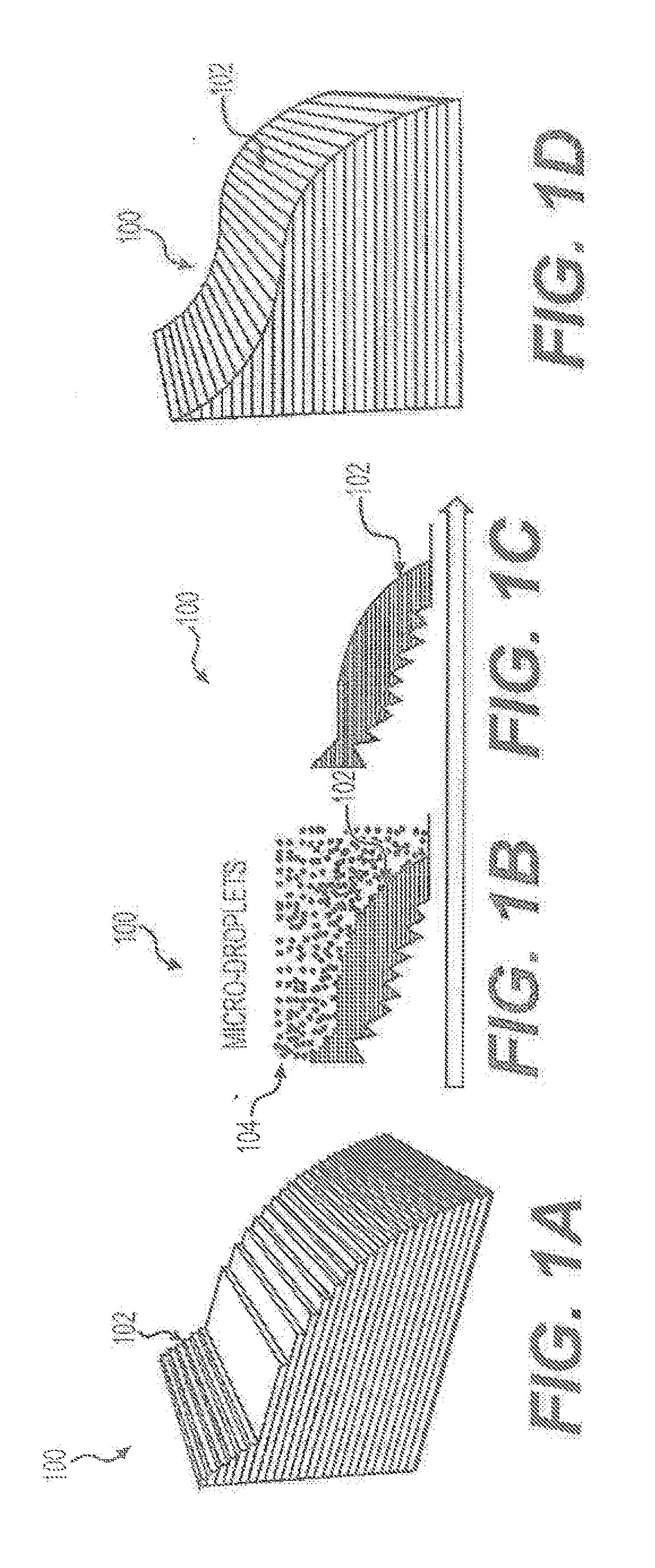
[0072]The extrudate, pulled by a puller at a constant speed, was cooled in a water tank, and collected on a spool. The puller speed was set to draw the filament to a final diameter of about 1.75 mm. The spooled filament was then dried before printing object 100.

[0073]In some embodiments, the material for making object...

example 2

Measurement of the Roughness of the Surface of Exemplary Objects 100

[0078]A compounded material was prepared for making exemplary objects 100 by (1) manually mixing all of the ingredients as shown in Table 2 in the formulation (2) melt compounding the ingredients using a 20 mm co-rotating twin-screw extruder under the conditions listed in Table 3, and (3) manufacturing the compounded material into a filament with an average diameter of 1.75 mm via single-screw extrusion, under the extrusion conditions listed in Table 4.

TABLE 2The formulation of a compounded materialfor making an exemplary object 100Content (phr*)PVB (B05HX from Chang Chun Group)100Anti-Oxidant (B215 from BASF)0.3Nitrile Rubber15(P35 from OMNOVA Solutions)*“phr” means parts per hundreds of resin.

TABLE 3Melt compounding conditionsFeed2nd3rd4thZoneZoneZoneZoneDieRPMTemperature (° C.)120160190200190120

TABLE 4Filament extrusion conditionsFeedCompressionMeteringZoneZoneZoneDieRPMTemperature (° C.)9017020019030

[0079]The re...

example 3

Processing 3D-Printed Object 100 Using an Exemplary Apparatus 200

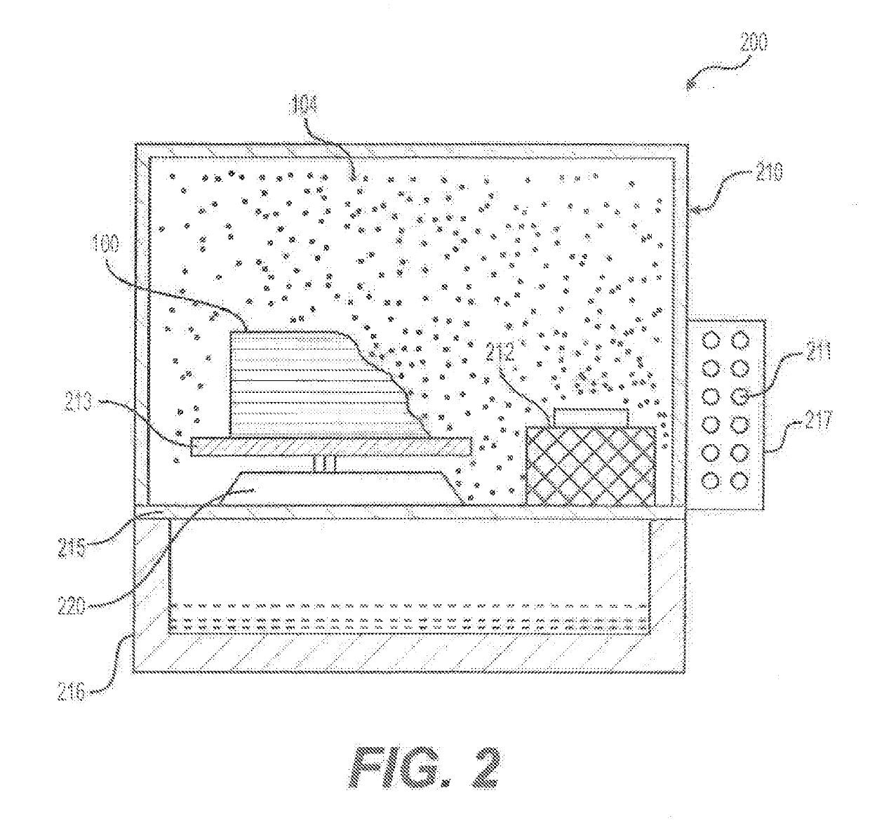
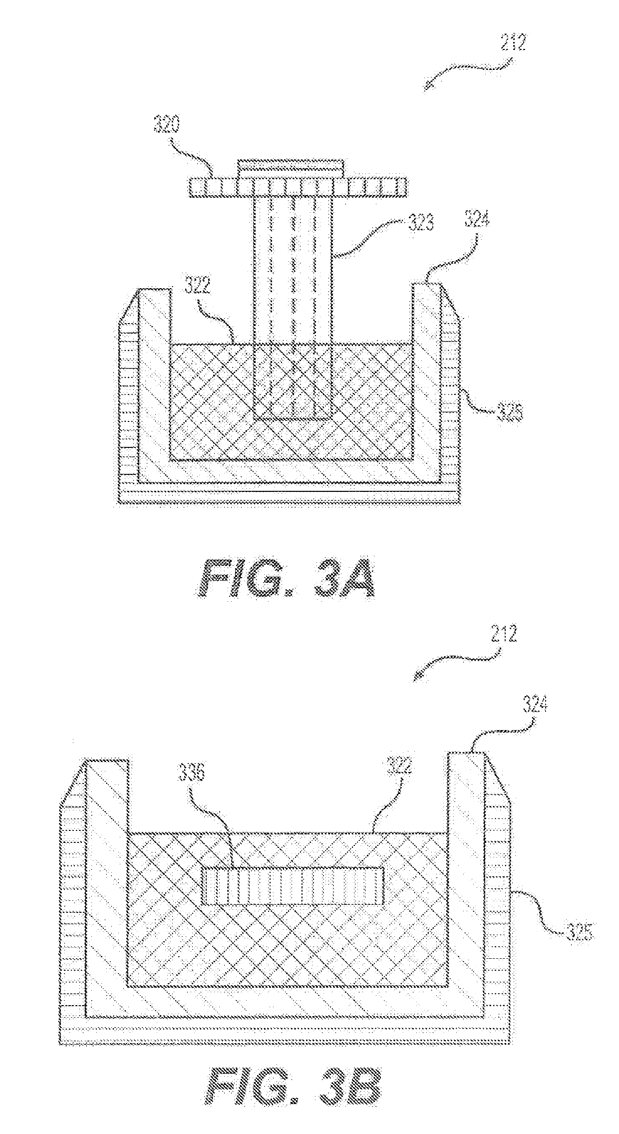
[0083]An exemplary apparatus 200 substantially similar to that shown in FIG. 2 was used. Apparatus 200 included an exemplary rotatable platform 213 for placing an exemplary 3D-printed 100, a nebulizing unit with two exemplary vibrating membrane nebulizers 212, and electrical circuits configured to power the nebulizing unit as well as the structural components.

[0084]An owl model (about 12 cm tall) was printed on a FlashForge Creator Pro desktop 3D printer using the filament prepared as described in Example 1, under the following printer settings: printing / nozzle temperature: 210° C.; build plate temperature: 60° C.; printing speed: 60 mm / s; layer height: 0.2 mm.

[0085]The printed owl model was processed or polished in apparatus 200 for about 40 min using isopropanol as an exemplary liquid 322. After processing or polishing, the owl model was removed from apparatus 200 and the surface of the owl model dried off under natu...


PUM

PropertyMeasurementUnit
diametersaaaaaaaaaa
diametersaaaaaaaaaa
diametersaaaaaaaaaa

Abstract

An apparatus (200) for smoothing a surface of an object (100). The apparatus includes a chamber (210), a reservoir (324) configured to hold a liquid (322), and a nebulizer assembly (212) configured to generate a mist (104) from the liquid into the chamber. The nebulizer assembly includes a mesh (732), a vibrating element (731), and a wick (736). The object is received in the chamber and the mist is configured to surround the object.

Description

CROSS-REFERENCE TO RELATED APPLICATION[0001]This application claims priority to and benefits of International Patent Application No. PCT / CN2015 / 081512, filed Jun. 16, 2015, which is incorporated herein by reference in its entiretyTECHNICAL FIELD[0002]Embodiments of the present disclosure are directed to methods and apparatuses for processing objects, and more particularly, to methods and apparatuses for processing objects created using additive manufacturing processes.BACKGROUND OF THE DISCLOSURE[0003]Additive manufacturing is any of various manufacturing technologies that build objects in an additive, typically layer-by-layer, fashion. Additive manufacturing is also referred to by the general public as “3D printing”. One type of the additive manufacturing technologies is based on extrusion deposition, such as fused deposition modeling® (FDM®) or fused filament fabrication (FFF). Over the last few years FDM® or FFF has become a commonly used technology for modeling, prototyping, and...

Claims


Application Information

Patent Timeline
Patent Type & Authority Applications(United States)
IPC IPC(8): B05C3/109B29C64/35B29C71/00B05C11/10
CPCB05C3/109B29C64/35B29C71/0009B05C11/1002B29C64/118B05B7/1666B05B7/2424B05B13/0242B05B17/0615B05B17/0684B29C64/30B33Y40/20B29C64/188
Inventor LUO, XIAOFANPEI, ZHAOKUNZHAO, JUNHENGTRUCHSESS, JULIA D.
Owner JF POLYMERS (SUZHOU) CO LTD
Why Eureka
Try Eureka