Image display device

a stereoscopic image and display device technology, applied in optics, instruments, electrical equipment, etc., can solve the problems of higher risk of disconnection in the transparent electrode, defective panels in which the parallax barrier does not operate correctly, and sense of discomfort in the observer, so as to reduce defectiveness, narrow the width of the sub-aperture, and suppress the increase of the frame area

Inactive Publication Date: 2019-05-23
TRIVALE TECH
View PDF3 Cites 2 Cited by
  • Summary
  • Abstract
  • Description
  • Claims
  • Application Information

AI Technical Summary

Benefits of technology

[0013]The present invention has an object to provide an image display device capable of reducing defectiveness caused by disconnection of a transparent electrode while narrowing the width of a sub-aperture formed in a parallax barrier shutter panel and suppressing increase of a frame area of the parallax barrier shutter panel.
[0015]According to the present invention, the transparent electrodes of the first transparent substrate receive input of the barrier control signals from both ends. Therefore, even if one of the first transparent electrodes is disconnected, the barrier control signals can be supplied to a portion beyond the disconnected portion, thus allowing the parallax barrier to operate correctly. Further, since the transparent electrodes are provided separately as the lower-layer transparent electrodes and the upper-layer transparent electrodes, the pitches of the transparent electrodes can be reduced. With this, the effective width of the sub-opening of the parallax barrier shutter panel can be reduced. Further, it is only necessary that the pattern of the common wires be disposed only on two sides (the first area and the second area) of the first transparent substrate. Therefore, the frame area of the parallax barrier shutter panel can be prevented from being extended.

Problems solved by technology

Particularly, frequent switching in the positions of the light-shielding part and of the left-eye image and the right-eye image due to frequent motion of the head of the observer raises a sense of discomfort in the observer.
However, Japanese Patent Application Laid-Open No. 2017-58682 does not disclose specific methods for increasing N.
A narrower width of the transparent electrode leads to a higher risk of disconnection in the transparent electrode due to a foreign matter or the like that may be generated during deposition and patterning of the transparent electrode.
The barrier control signal is not supplied to a portion beyond a disconnected portion of the transparent electrode once the transparent electrode is disconnected, which may produce a defective panel in which a parallax barrier does not operate correctly.
Such a problem also occurs when the pitches of the sub-pixels are reduced for the purpose of achieving higher resolution or downsizing of the stereoscopic image display device,
However, in order to employ such a configuration, wiring for the barrier control signals is required to be formed on at least three sides of the panel, which hinders narrowing the frame and downsizing of the panel.
Further, if the wiring is extended, influence of static electricity from the periphery of the panel is increased, and a short circuit is therefore prone to occur between wires and between electrodes due to electric discharge inside the panel.

Method used


Image

  • Image display device
  • Image display device
  • Image display device

Examples


first preferred embodiment

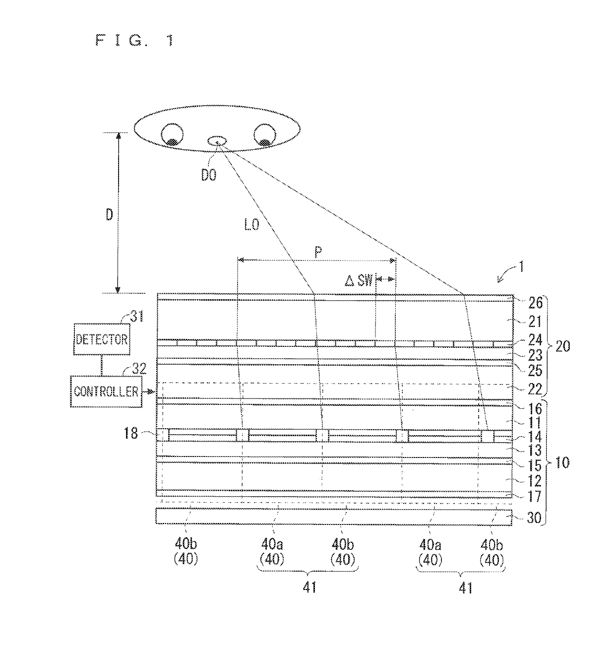
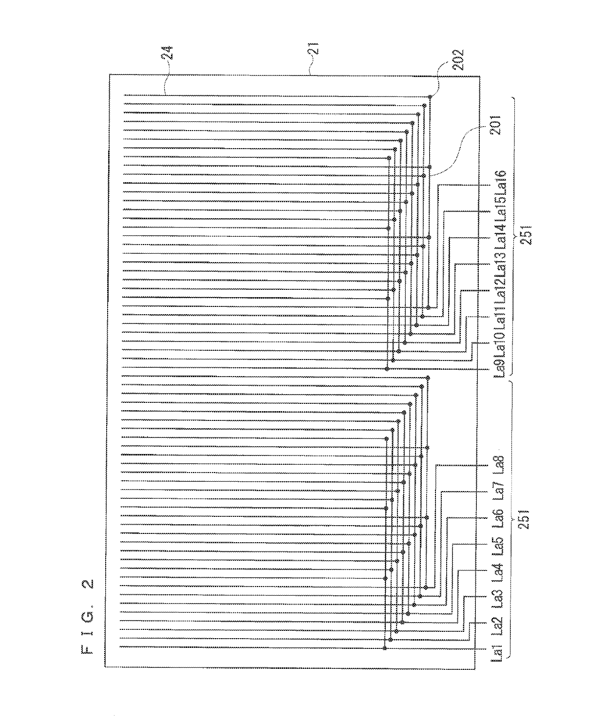
[0068]The overall configuration of an image display device 1 according to a first preferred embodiment of the present invention is similar to that of FIG. 1. Although not shown in FIG. 1, the image display device 1 of the first preferred embodiment has a different feature from the above underlying technology in the structure of a first transparent substrate 21 of a parallax barrier shutter panel 20. Therefore, the configuration of the first transparent substrate 21 in particular will be described in this preferred embodiment. The configuration of a second transparent substrate 22 may be the same as that of the underlying technology. Here, a second transparent electrode 25 is formed across the entire surface of the second transparent substrate 22.

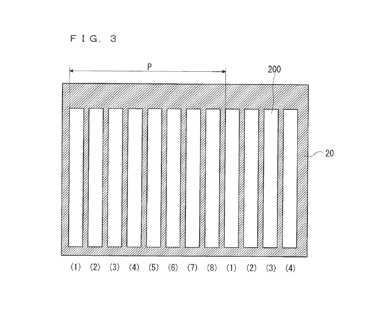
[0069]Further, in this preferred embodiment, the number of sub-apertures 200, i.e., the number of first transparent electrodes 24, to be provided within a reference parallax barrier pitch P is eight, Note that, the number of sub-apertures 20...

second preferred embodiment

[0107]FIG. 16 is a plan view illustrating an overall configuration of the first transparent substrate 21 of the parallax bather shutter panel 20 according to a second preferred embodiment. FIG. 17 is a partial enlarged plan view of the counter-input-side connection area 56 of the first transparent substrate 21 of the parallax barrier shutter panel 20 according to the second preferred embodiment. FIG. 18 is a cross-sectional view taken along the line F-F illustrated in FIG. 17.

[0108]As illustrated in FIG. 6 and FIG. 9, in the counter-input-side connection area 56 according to the first preferred embodiment, the first transparent electrodes 24 (the lower-layer transparent electrodes 24a and the upper-layer transparent electrodes 24b) that receive input of the same barrier control signal are electrically connected one another via the common wires 204. In contrast, in the second preferred embodiment, as in FIG. 16 and FIG. 17, the first transparent electrodes 24 (the lower-layer transpa...

third preferred embodiment

[0119]FIG. 23 is a plan view illustrating an overall configuration of the first transparent substrate 21 of the parallax barrier shutter panel 20 according to a third preferred embodiment. FIG. 24 is a partial enlarged plan view of the counter-input-side connection area 56 of the first transparent substrate 21 of the parallax barrier shutter panel 20 according to the third preferred embodiment.

[0120]In the above second preferred embodiment, the common wires 204 disposed in the counter-input-side connection area 56 are not connected to any of the first transparent electrodes 24 (the lower-layer transparent electrodes 24a and the upper-layer transparent electrodes 24b) so as to be floated. In the third preferred embodiment, however, at least one first transparent electrode 24 is connected to each common wire 204.

[0121]The first transparent electrodes 24 that are connected to different common wires 204 receive input of different barrier control signals. Thus, each common wire 204 is su...


PUM


Abstract

A first transparent substrate of a parallax barrier shutter panel includes, in a display area, lower-layer transparent electrodes disposed below an interlayer insulation film and upper-layer transparent electrodes disposed on the interlayer insulation film as vertically extending first transparent electrodes. The first transparent substrate includes, in an input-side connection area adjacent to the display area, a wire for inputting a barrier control signal that is output from a drive IC into the first transparent electrodes. The first transparent substrate includes, in a counter-input-side connection area adjacent to the display area on an opposite side to the input-side connection area with respect to the display area, a common wire for connecting first transparent electrodes that receive input of the same barrier control signal.

Description

BACKGROUND OF THE INVENTIONField of the Invention[0001]The present invention relates to a naked eye stereoscopic image display device or a dual-screen display device of a parallax barrier type.Description of the Background Art[0002]Hitherto, a naked-eye stereoscopic image display device that allows stereoscopic view without the need of special eyeglasses has been proposed. For example, Japanese Patent Application Laid-Open No. 3-119889 (1991) discloses a stereoscopic image display device. The stereoscopic image display device includes barrier generating means for generating parallax barrier stripes through electronic control using a transmission display element, a display screen disposed behind and away from a position of generating the parallax barrier stripes, and image display means for outputting and displaying a multi-directional image onto the display screen, the multi-directional image including strips for a left image and a right image that are alternately arrayed correspond...

Claims


Application Information

Patent Timeline
Patent Type & Authority Applications(United States)
IPC IPC(8): H04N13/315H04N13/376H04N13/15H04N13/349G02B27/22G02B30/31
CPCH04N13/315H04N13/376H04N13/15H04N13/349G02B27/2214H04N2213/001G02B30/31G02B30/27
Inventor MIYAKAWA, OSAMU
Owner TRIVALE TECH
Why Eureka
Try Eureka