Method and device for transmitting uplink information

a technology of uplink information and transmission method, which is applied in the direction of wireless network protocols, power management, wireless communication, etc., can solve the problems of power adjustment of devices that need a transition time and the need for transmission power of devices, so as to reduce the probability of collisions between devices

Active Publication Date: 2019-05-23
SAMSUNG ELECTRONICS CO LTD
View PDF2 Cites 11 Cited by
  • Summary
  • Abstract
  • Description
  • Claims
  • Application Information

AI Technical Summary

Benefits of technology

[0058]By adopting the method of the present disclosure, the total uplink transmission power of an entire cell in one sub-frame can be controlled, so as to realize coexistence with other devices, and by reasonably setting an LBT time period and a power increase conversion time, the probability of collisions among devices can be reduced.

Problems solved by technology

In fact, power adjustments of devices need a transition time.
However, the transmission power of the device is required to reach a required value after the transition time.

Method used


Image

  • Method and device for transmitting uplink information
  • Method and device for transmitting uplink information
  • Method and device for transmitting uplink information

Examples


first example

A First Example

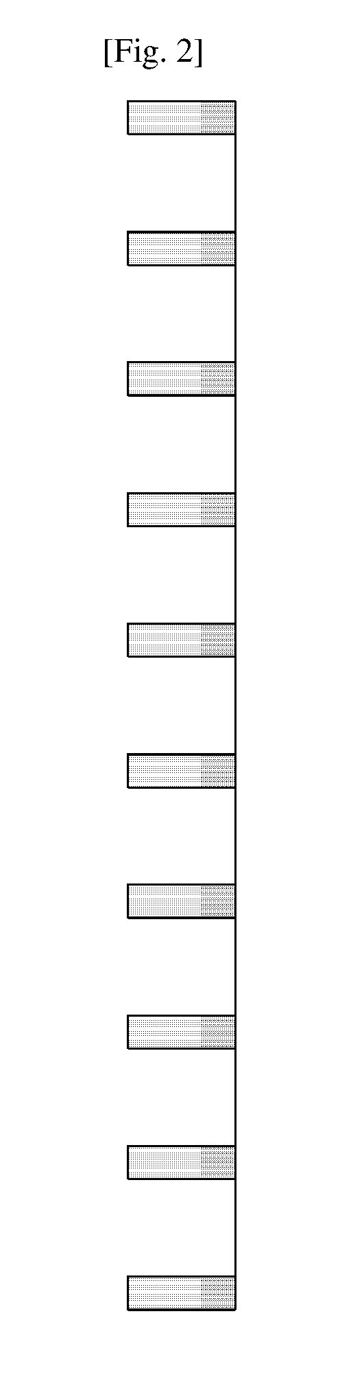
[0087]On one carrier of an unlicensed band, an allocation granularity of an uplink PUSCH channel of the UE is one interlace. One interlace contains multiple PRBs, and these PRBs are dispersed on the whole band. For example, FIG. 2 shows that it is assumed that one interlace includes 10 PRBs which are distributed at equal intervals on the whole band of 20 MHz. The uplink PUSCH of the UE needs to meet the requirements of a maximum transmission power in one aspect and needs to meet the limitation of the PSD in the other aspect. The PUSCH resource allocation structure based on interlaces may be adopted relaying on a definition method of the frequency granularity of the PSD. When the frequency granularity is large, for example, 1 MHz, the allowed maximum transmission power of the UE may be increased. For example, it is assumed that the frequency granularity of the PSD is 1 MHz and the limitation of the PSD is 10 dBm / MHz, the transmission power on one PRB of one interlace m...

second example

A Second Example

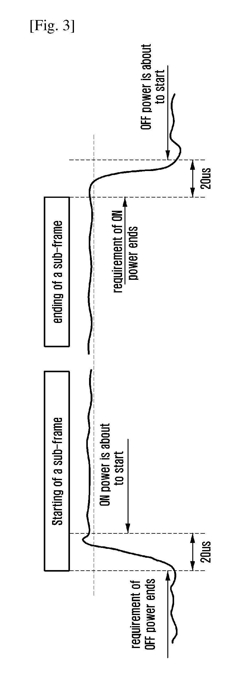
[0103]Due to limitations of the device, the transition time during power adjusting of the device always exists in actual working environments. And the transition time includes a power increase transition time and a power decrease transition time. In the existing LTE systems, positions of the power increase transition time of different types of signals relative to a sub-frame / OFDM signal are different. That is, for a PUSCH, the power increase transition time of the UE is 20 us after the start time of the uplink transmission scheduled by the base station; for a PRACH and an SRS, the power increase transition time of the UE is 20 us before the start time of the PRACH and the SRS. According to the 3GPP RAN4 specifications, there are no requirements on the instantaneous value of the transmission power of the device in the transition time. However the transmission power of the device is required to reach a required value after the transition time.

[0104]On a carrier of an u...

third example

A Third Example

[0117]Due to limitations of the device, a transition time of power adjusting of the device during actual working process is needed. The transition time may include a power increase transition time and a power decrease transition time. In the existing LTE systems, for a PUSCH, a PRACH and an SRS, the power decrease transition time of the UE is 20 us after the ending of corresponding uplink transmission. According to the 3GPP RAN4 specification, there are no requirements on the instantaneous value of the transmission power of the device in the transition time, but the transmission power of the device needs to reach a required value after the transition time.

[0118]On a carrier of an unlicensed band, the UE contends for a channel by executing LBT, and starts uplink transmission after completing LBT successfully. The above LBT may be CAT2 or CAT4. In addition, the LBT may also be NO LBT. For the power decrease transition time, the transmission power of the UE needs to be d...


PUM


Abstract

The present disclosure relates to a communication method and system for converging a 5th-Generation (5G) communication system for supporting higher data rates beyond a 4th-Generation (4G) system with a technology for Internet of Things (IoT). The present disclosure may be applied to intelligent services based on the 5G communication technology and the IoT-related technology, such as smart home, smart building, smart city, smart car, connected car, health care, digital education, smart retail, security and safety services. The present application provides a method for transmitting uplink information, which includes the following: a UE detects control information, i.e., UL-Grant for scheduling uplink data transmissions from a base station; determines according to the control information, the number of PRBs resource allocated by the base station, determining a maximum transmission power allowed in the current sub-frame, determines an uplink transmission power of the UE; executes an LBT according to UL-Grant configurations, and starts an uplink data transmission after the LBT is successful. By adopting the method of the present disclosure, the total uplink transmission power of an entire cell in one sub-frame is controlled, so as to realize coexistence with other devices. Further, by reasonably setting an LBT time period and power increase transition time, the probability of collisions among devices is reduced.

Description

TECHNICAL FIELD[0001]The present disclosure relates to wireless communication technologies, in particular to a method and device for transmitting uplink information on an unlicensed band.BACKGROUND ART[0002]To meet the demand for wireless data traffic having increased since deployment of 4G communication systems, efforts have been made to develop an improved 5G or pre-5G communication system. Therefore, the 5G or pre-5G communication system is also called a ‘Beyond 4G Network’ or a ‘Post LTE System’. The 5G communication system is considered to be implemented in higher frequency (mmWave) bands, e.g., 60 GHz bands, so as to accomplish higher data rates. To decrease propagation loss of the radio waves and increase the transmission distance, the beamforming, massive multiple-input multiple-output (MIMO), Full Dimensional MIMO (FD-MIMO), array antenna, an analog beam forming, large scale antenna techniques are discussed in 5G communication systems. In addition, in 5G communication syste...

Claims


Application Information

Patent Timeline
Patent Type & Authority Applications(United States)
IPC IPC(8): H04W52/36H04W74/08H04W52/14H04W72/14H04W72/04H04W80/08H04W74/02
CPCH04W52/367H04W74/0816H04W52/14H04W72/14H04W72/0473H04W72/0446H04W80/08H04W74/02H04W52/146H04W52/346H04W74/0808H04W52/08H04W72/23H04W52/36
Inventor LI, YINGYANGWANG, YIZHANG, SHICHANG
Owner SAMSUNG ELECTRONICS CO LTD
Why Eureka
Try Eureka