Synthesizer and phase frequency detector

a phase frequency detector and synthesizer technology, applied in the direction of angle modulation, electrical apparatus, pulse automatic control, etc., can solve the problem that the two-point modulated phase locked loop can only approximate a linear frequency modulation with discrete frequency steps, and unwanted ghost targets in radar images, etc., to achieve the effect of limited phase detection range and high phase accuracy

Active Publication Date: 2019-05-30
SONY CORP
View PDF0 Cites 4 Cited by
  • Summary
  • Abstract
  • Description
  • Claims
  • Application Information

AI Technical Summary

Benefits of technology

[0012]One of the aspects of the disclosure is to use a novel synthesizer concept with two cascaded PLLs, which can e.g. be manufactured in CMOS technology as integrated circuitry. The synthesizer comprises a two point modulated PLL, generating the intermediate frequency. This signal drives a second PLL, which preferably includes a fast subsampling phase detector (SSPD) and dead zone PFD. From the input stepwise increasing frequency signal, the second PLL generates a straightened, almost linearly increasing frequency signal in the mm-wave region. Further, high phase accuracy may be achieved by use of the SSPD. The provided synthesizer enables FMCW signal (i.e. chirp signal) generation for radar applications.
[0013]The dead zone PFD may be advantageously used in a synthesizer according to the present disclosure or in other synthesizers comprising a PLL, e.g. having a subsampling phase detector (with limited phase detection range). It provides for adjustment of the frequency. After frequency adjustment the PLL, e.g. the subsampling PLL in a synthesizer according to the present disclosure, supports further phase tuning of the PLL.

Problems solved by technology

However, these synthesizers are limited with respect to chirp speed.
However, two-point modulated phase locked loops can only approximate a linear frequency modulation with discrete frequency steps.
This impairment leads to unwanted ghost targets in the radar image.

Method used


Image

  • Synthesizer and phase frequency detector
  • Synthesizer and phase frequency detector
  • Synthesizer and phase frequency detector

Examples


first embodiment

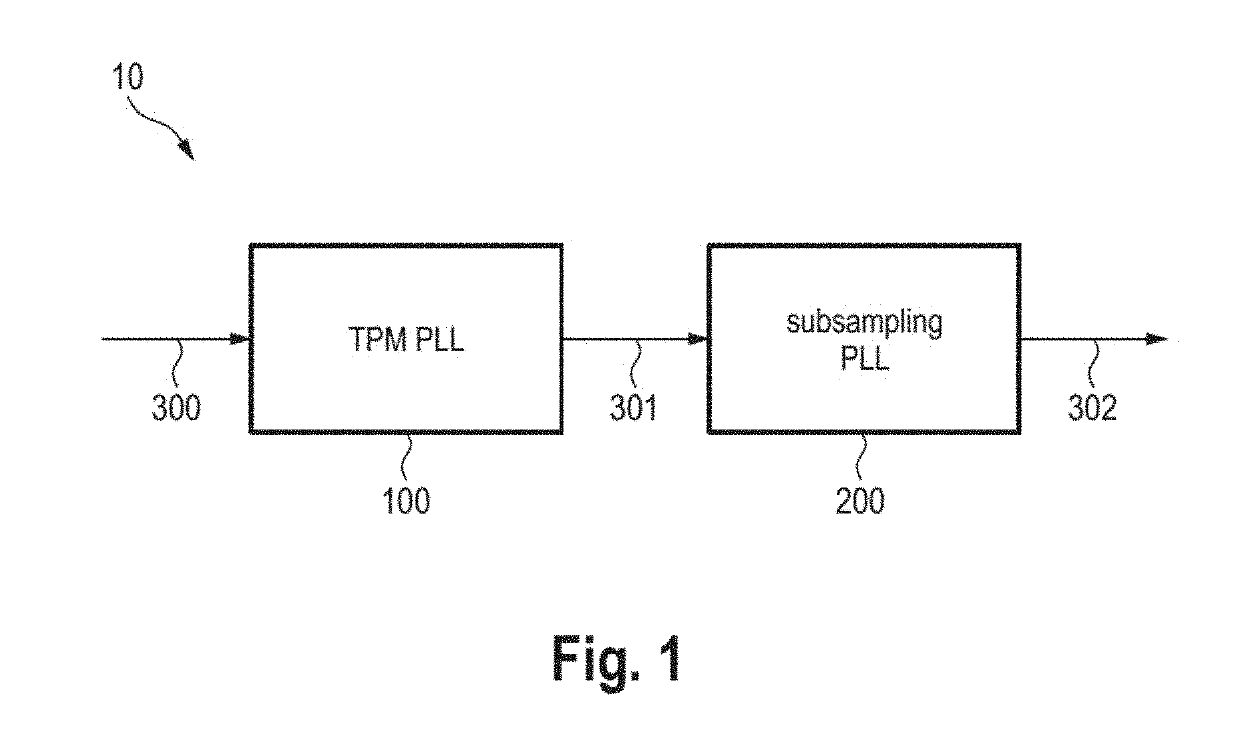
[0030]Referring now to the drawings, wherein like reference numerals designate identical or corresponding parts throughout the several views, FIG. 1 shows a synthesizer 10 according to the present disclosure. The synthesizer 10 comprises a two-point modulation (TPM) phase locked loop (PLL) circuit 100 and a subsampling PLL circuit 200. The TPM PLL circuit 100 is configured to receive a frequency tuning signal 300 and to generate a stepped chirp signal 301 in an intermediate frequency range by applying a two-point modulation PLL on the frequency tuning signal 300. The subsampling PLL circuit 200 is configured to receive the stepped chirp signal 301 and to generate a smoothened chirp signal 302 in a mm-wave frequency range by applying a subsampling PLL on the stepped chirp signal 301.

[0031]In fractional-n PLL synthesizers the phase is unlocked when fast chirps are synthesized by the PLL. Hence, fractional-n PLL architectures cannot fulfill the future requirements of the automotive ind...

second embodiment

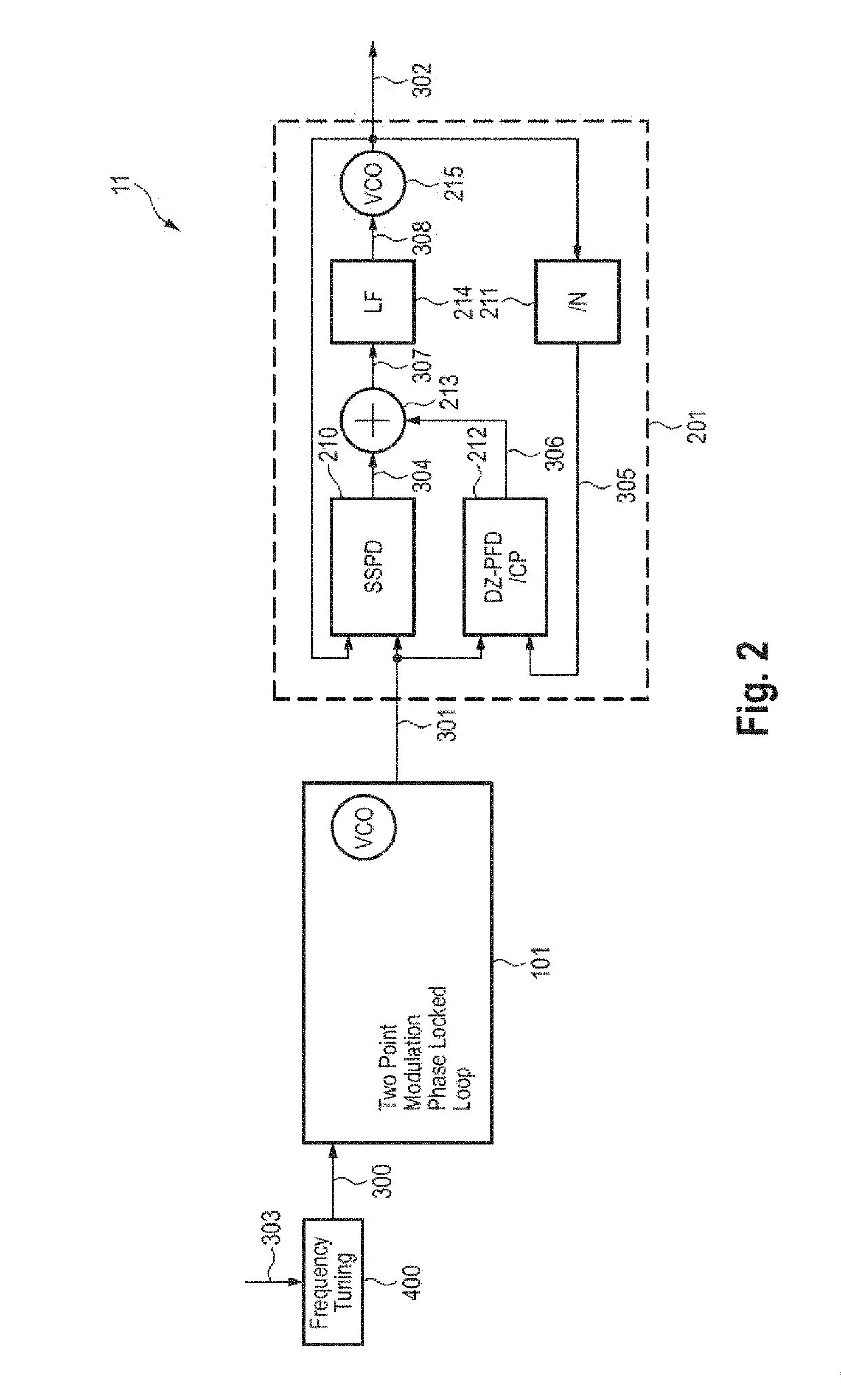
[0033]FIG. 2 shows a schematic diagram of a synthesizer 11 according to the present disclosure. A fast-stepped frequency FMCW chirp signal 301 is generated by the TPM PLL circuit 101. The TPM PLL circuit 101 can be implemented as an analogue, partly digital or all digital PLL. The output signal 301 of the TPM PLL is applied as reference signal to the subsampling PLL circuit 201. The subsampling PLL circuit 201 converts the intermediate frequency chirp signal 301 (e.g. in the range of 100 MHz to 10 GHz) to the mm-wave domain (e.g. in the range of 30-300 GHz). The input signal 301 of the second PLL circuit 201 is a chirp signal stepwise increasing its frequency. However due to the smoothing characteristic of the second PLL circuit 301 a highly linear chirp 302 is generated. The bandwidths of the PLLs 101, 201 are tuned towards optimal phase noise.

[0034]A frequency tuner 400 is additionally provided for generating a stepped frequency tuning signal 300 from a tuning signal (reference si...

third embodiment

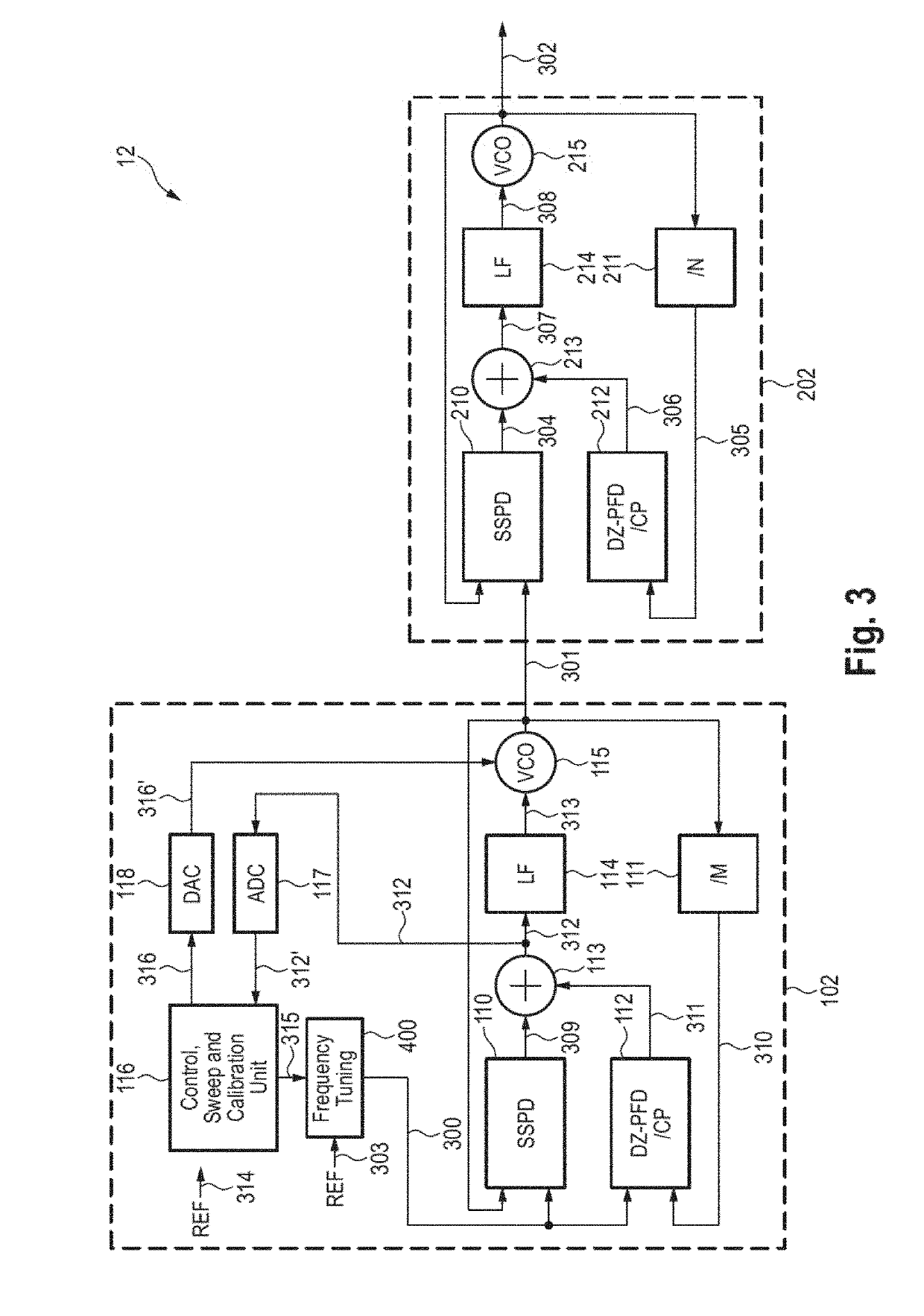
[0037]FIG. 3 shows a schematic diagram of a synthesizer 12 according to the present disclosure. The subsampling PLL circuit 202 is substantially identical to the subsampling PLL circuit 201 shown in FIG. 2. Further, an exemplary analog TPM PLL circuit 102 is employed to synthesize the stepped frequency signal 301.

[0038]The TPM PLL circuit 102 comprises a first phase detector circuit 110 (SSPD) configured to receive the frequency tuning signal 300 and the stepped chirp signal 301 and to generate a first phase detection signal 309. A first frequency divider 111 ( / M) applies a frequency division on the stepped chirp signal 301. A first phase-frequency detector and charge pump circuit 112 (DZ-PFD / CP) receives the frequency tuning signal 300 and the stepped chirp signal 310 after application of the frequency-division and generates a second phase detection signal 311.

[0039]The TPM PLL circuit 102 further comprises a combiner 113 configured to combine the first phase detection signal 309 a...


PUM


Abstract

A synthesizer comprises a two-point modulation phase locked tow, TPM PLL, circuit configured to receive a frequency tuning signal and to generate a stepped chirp signal in an intermediate frequency range by applying a two-point modulation PLL on the frequency tuning signal, and a subsampling PLL circuit configured to receive the stepped chirp signal in a mm-wave frequency range and to generate a smoothened chirp signal in a mm-wave frequency range by applying a subsampling PLL on the stepped chirp signal.

Description

CROSS-REFERENCE TO RELATED APPLICATION[0001]This application claims priority to the European Patent Application No. 17204714.4 on 30 Nov. 2017, the entire contents of which being incorporated herein by reference.BACKGROUNDField of the Disclosure[0002]The present disclosure relates to a synthesizer and a phase frequency detector.Description of Related Art[0003]Fast chirp modulation schemes are required for future radars. Current Frequency-Modulated Continuous-Wave (FMCW) synthesizers employ fractional-n PLL synthesizers. However, these synthesizers are limited with respect to chirp speed. Two point modulated synthesizers overcome these problems as the PLL remains locked during the entire chirp sequence. However, two-point modulated phase locked loops can only approximate a linear frequency modulation with discrete frequency steps. This impairment leads to unwanted ghost targets in the radar image.[0004]The “background” description provided herein is for the purpose of generally prese...

Claims


Application Information

Patent Timeline
Patent Type & Authority Applications(United States)
IPC IPC(8): H03L7/087
CPCH03L7/087H03L7/18H03C3/0941H03C3/0958H03C3/0966H03L7/089H03L7/091H03L7/113H03L7/22H03L7/23
Inventor OTT, ARNDT THOMASKREMPIG, MATHIAS
Owner SONY CORP
Why Eureka
Try Eureka