Check patentability & draft patents in minutes with Patsnap Eureka AI!

Flight vehicle air breathing engine with isolator containing flow diverting ramps

Active Publication Date: 2019-06-06
RAYTHEON CO
View PDF0 Cites 2 Cited by
  • Summary
  • Abstract
  • Description
  • Claims
  • Application Information

AI Technical Summary

Benefits of technology

The flight vehicle engine isolator described in this patent improves flow mixing by using a special design that helps to mix high energy flow with lower energy flow. This design also reduces the separation zone within the isolator, which can improve engine performance.

Problems solved by technology

This pressure rise must not allow pressure communications to travel through the isolator boundary layer and upstream past the inlet throat or allow the shock train to extend upstream of the inlet throat, both potentially resulting in unstart of the inlet.
These strong shock interactions with weak boundary layers can result in lower pressure-rise capability and / or high distortion of the flow profile (mass flux, Mach Number, total pressure, etc.) at the isolator exit, which will be ingested by the engine and may reduce combustion efficiency or cause engine stall / flame-out.
Integrated airbreathing hypersonic vehicles usually suffer from highly distorted flow profiles at the combustor face, which is known to reduce combustion efficiency substantially and has the effect of reducing the vehicle's range and acceleration capabilities.
Also, separated regions induced by strong shock-wave boundary layer interactions during isolator back pressured conditions, especially in isolators with oblique shock train systems, can cause separation zones in the isolator to propagate to the combustor face.
This opens-up the possibility for combustion gases to become entrained in the isolator with high potential to cause a burn-through of the isolator.

Method used


Image

  • Flight vehicle air breathing engine with isolator containing flow diverting ramps
  • Flight vehicle air breathing engine with isolator containing flow diverting ramps
  • Flight vehicle air breathing engine with isolator containing flow diverting ramps

Examples


Embodiment Construction

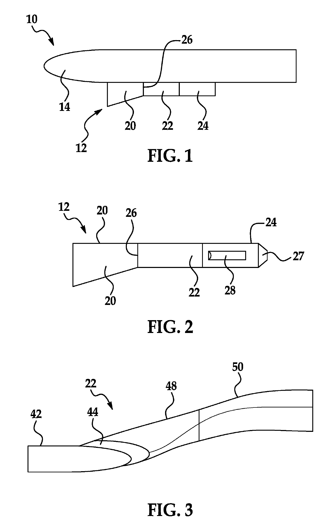
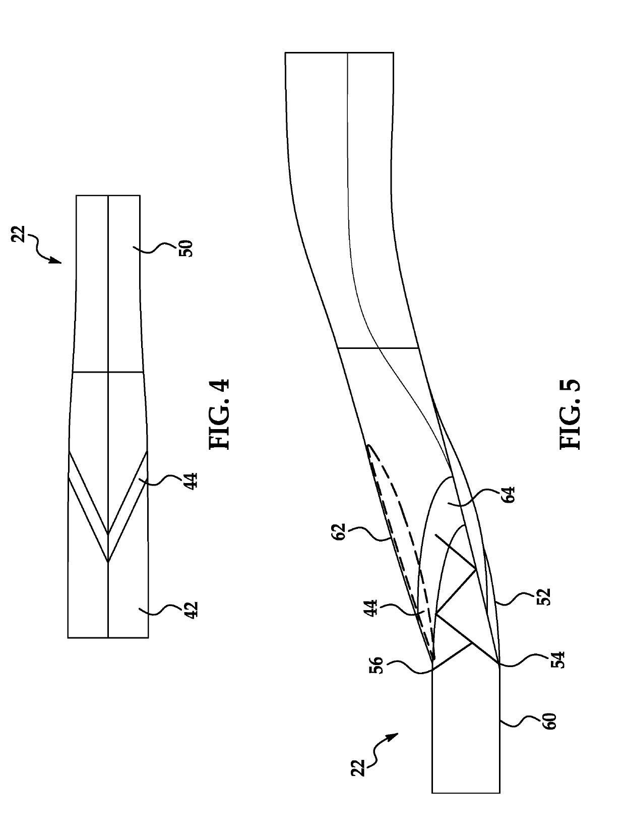
[0047]A flight vehicle engine includes an isolator with a swept-back wedge to improve flow mixing. The wedge includes forward shock-anchoring locations, such as edges or rapidly-curved portions, that anchor oblique shocks in situations where the isolator has sufficient back pressure. The swept-back wedge may also create swept oblique shocks along its length. Boundary layer flow streamlines are diverted running parallel to or parallel but moving outward conically to the swept-wedge leading edge moving outboard and upward. This flow may create and propagate vortices as well, which may increase the energy of this flow and folds-in high energy non-viscous flow. The non-viscous flow outside the boundary layer is processed through the swept-back ramp shock and diverted outboard and upward as well, with velocity vectors consistent with the swept-back wedge geometry and incoming flow conditions. The outboard aft portion of the wedge close to and at the sidewall intersection may also induce ...


PUM


Abstract

A flight vehicle engine includes an isolator with a swept-back wedge to improve flow mixing. The wedge includes forward shock-anchoring locations, such as edges or rapidly-curved portions, that anchor oblique shocks in situations where the isolator has sufficient back pressure. The swept-back wedge may also create swept oblique shocks along its length. Boundary layer flow streamlines are diverted running parallel to or parallel but moving outward conically to the swept-wedge leading edge moving outboard and upward. The non-viscous flow outside the boundary layer is processed through the swept-back ramp shock and diverted outboard and upward as well. The outboard aft portion of the wedge at the sidewall intersection may also induce shocks and divert flow near the walls closer toward the walls and upward, and / or improve flow mixing.

Description

GOVERNMENT LICENSE RIGHTS[0001]This invention was made with government support under contract HR0011-17-C-0025 awarded by the United States Department of Defense. The government has certain rights in the invention.FIELD OF THE INVENTION[0002]The invention is in the field of engines for flight vehicles such as airplanes, missiles, projectiles or access-to-space systems.DESCRIPTION OF THE RELATED ART[0003]Supersonic and hypersonic air-breathing engines, such as dual-mode ramjets / scramjets, include isolators. The isolator is typically a constant-area or slightly-monotonically-increasing area section located downstream of an air inlet throat, between the inlet and an engine / combustor. The purposes for the isolator may be to separate fluctuations between conditions in the inlet and the combustor, to provide a desired flow profile to the combustor, to reduce problems with inlet unstart and / or combustion stability. The isolator may also provide additional pressure rise upstream of the comb...

Claims


Application Information

Patent Timeline
IPC IPC(8): F02K7/10F02K7/08B64D27/20
CPCF02K7/10F02K7/08B64D27/20F05D2220/10F02K7/00F02C7/04F42B10/38F42B10/42F42B15/10B64D2033/026B64D33/02B64C30/00Y02T50/60B64C23/04F05D2250/51F05D2220/80
Inventor CICCHINI, NICHOLAS P.
Owner RAYTHEON CO
Features
  • R&D
  • Intellectual Property
  • Life Sciences
  • Materials
  • Tech Scout
  • Unparalleled Data Quality
  • Higher Quality Content
  • 60% Fewer Hallucinations
Learn More