Photoreceptor, flight time measurement device, and optical radar

a flight time measurement device and optical radar technology, applied in measurement devices, using reradiation, instruments, etc., can solve problems such as errors in assembly of flight time measurement devices, optical radar devices that cannot achieve efficient optical radar devices, and inability to extend the maximum range distance under intense background ligh

Active Publication Date: 2019-06-06
SHARP KK
View PDF4 Cites 6 Cited by
  • Summary
  • Abstract
  • Description
  • Claims
  • Application Information

AI Technical Summary

Problems solved by technology

On the other hand, light emission intensity is improved by the line-shaped laser light and scanning in only one direction (Japanese Unexamined Patent Application Publication No. 2016-161438) as compared to single-emission, but is still insufficient.
However, the above-described conventional optical radar devices have not been able to realize an optical radar device that can efficiently measure long distances and that also is inexpensive, due to the following reasons.
In automotive applications, flight time measurement devices have to operate even under midday sunlight at the equator, and extending the maximum ranging distance under intense background light is an issue.
However, assembly of the flight time measurement device involves error, and there is variance in the relative positions of the photodetector and light emitter.
On the other hand, the later increases assembly costs.
There is no photodetector currently available that can increase the maximum flight distance while reducing manufacturing costs.

Method used


Image

  • Photoreceptor, flight time measurement device, and optical radar
  • Photoreceptor, flight time measurement device, and optical radar
  • Photoreceptor, flight time measurement device, and optical radar

Examples


first embodiment

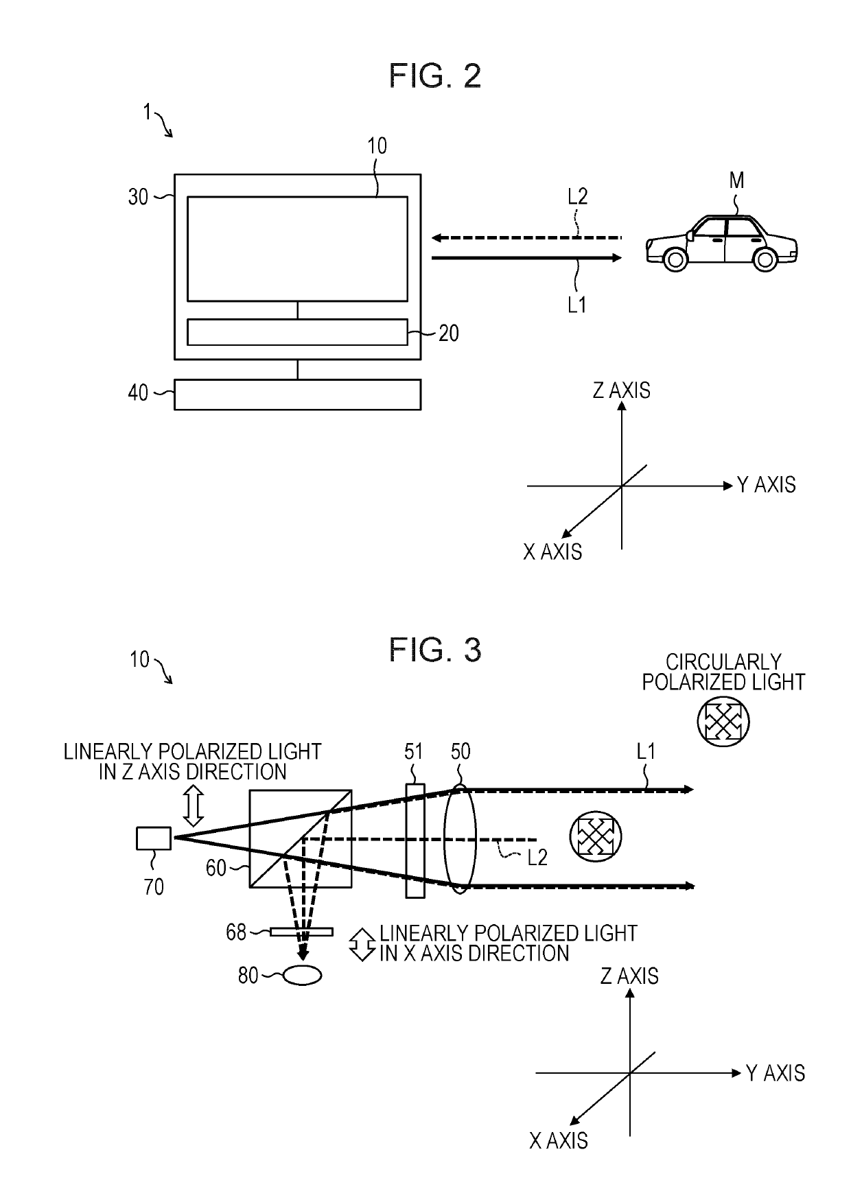
[0045]An embodiment of the present disclosure will be described with reference to FIGS. 1 through 13. The configuration of an optical radar device 1 having a flight time measurement device 10 according a first embodiment of the present disclosure will be described with reference to FIG. 2. FIG. 2 is a schematic diagram illustrating the configuration of the optical radar device 1 according to the present embodiment.

[0046]As illustrated in FIG. 2, the optical radar device 1 includes the flight time measurement device 10 that illuminates an object M by pulse light L1 and receives reflected light L2 from the object M, a control-and-power-source unit 20 that supplies electric power to the flight time measurement device 10 and controls the timing of emitting pulse light and of receiving light, and a housing 30 that accommodates the flight time measurement device 10 and control-and-power-source unit 20. The optical radar device 1 also has a driving-and-interfacing unit 40 that rotates the ...

first modification

[0126]The configuration of an optical radar device 1a that is a first modification of the optical radar device 1 according to the first embodiment will be described with reference to FIG. 12. FIG. 12 is a schematic diagram illustrating the configuration of the optical radar device 1a in the first modification of the first embodiment.

[0127]The optical radar device 1a differs from the optical radar device 1 with regard to the point that the measurement region is scanned by a reflecting mirror instead of a rotating mechanism, as illustrated in FIG. 12. However, a flight time measurement device 10a has the same functions as the flight time measurement device 10. The housing 30a does not nave to be rotated, so reduction in size, weight, and electric power consumption is easy. The reflecting mirror is good in that two-dimensional scanning can be performed.

[0128]In detail, the optical radar device 1a according to the first modification includes the flight time measurement device 10a that i...

second modification

[0133]The configuration of an optical radar device 1b that is a second modification of the optical radar device 1 according to the first embodiment will be described with reference to FIG. 13. FIG. 13 is a schematic diagram illustrating the configuration of the optical radar device 1b according to the second modification of the first embodiment.

[0134]The optical radar device 1b differs from the optical radar device 1 with regard to the point that the measurement region is scanned by a polygon mirror instead of a rotating mechanism, as illustrated in FIG. 13. However, a flight time measurement device 10b has the same functions as the flight time measurement device 10. The housing 30b does not have to be rotated, so reduction in size, weight, and electric power consumption is easy. The polygon mirror is good in that two-dimensional scanning can be performed.

[0135]In detail, the optical radar device 1b according to the second modification includes the flight time measurement device 10b...


PUM


Abstract

A photodetector measures flight time by an imaging optical element imaging reflected light from an illuminated illumination region of an object illuminated by pulse light, and a light detection portion receiving the imaged light. The light detection portion is formed larger than a projection region reflected at the illumination region of the object and imaged on the light detection portion. In the light detection portion, a portion overlaying the projection region is activated as a light-detection region.

Description

BACKGROUND1. Field[0001]The present disclosure relates to an optical radar that measures distance to an object, a flight time measurement device used in the same, and a photodetector used in the same.2. Description of the Related Art[0002]Three-dimensional imaging is a concept that includes, in addition to normal two-dimensional imaging of photographs and so forth, information of distance to an object within a field of view, and application of peripheral recognition in automobiles, robots, and so forth, is spreading in recent years. A method of emitting a laser light and measuring the flight time (time-of-flight) until the laser light reflects off an of and returns is becoming common place as a high-precision distance information measurement method.[0003]Methods of emitting a laser light toward a field of view include rotation systems where a laser light (spot beam) collimated to approximately parallel and emitted within a narrow range is rotated integrally with a light receiving de...

Claims


Application Information

Patent Timeline
Patent Type & Authority Applications(United States)
IPC IPC(8): G01S7/499G01S17/10G01S7/484G01S7/486G01S7/4863
CPCG01S7/499G01S17/10G01S7/484G01S7/4863G01S17/48G01S7/4816G01S7/4812G01S7/4817
Inventor IGUCHI, KATSUJIKAWANISHI, HIDENORITAKAHASHI, KOJIFUJII, NORIAKI
Owner SHARP KK
Why Eureka
Try Eureka