Medical implant and method for heart valve repair

a technology of heart valve and implant, applied in the surgical field, can solve the problems of poor quality, high dependence on operation success, and serious heart valve dysfunction, and achieve the effect of reliable and tissue-compliant repair, easy implanting and reliable operation

Active Publication Date: 2019-06-13
COREMEDIC
View PDF3 Cites 24 Cited by
  • Summary
  • Abstract
  • Description
  • Claims
  • Application Information

AI Technical Summary

Benefits of technology

[0006]It is an object of the present invention to provide an implant for repairing an atrioventricular, in particular the mitral or also the tricuspid, heart valve, and an according method, which

Problems solved by technology

Prolapses of a leaflet of the mitral valve into the left atrium and resulting valve insufficiency can cause serious dysfunctions of the heart.
One reason for such prolapse is a damaging of the tendons (chordae tendineae) that connect the leaflets of the mitral valve to the papillary muscle through the left ventricle.
A first disadvantage of such a repair process is that it is only possible while the heart is inactive, thus the surgical repair demands that the heart is stopped and drained of blood, while a cardiopulmonary bypass

Method used


Image

  • Medical implant and method for heart valve repair
  • Medical implant and method for heart valve repair

Examples


Embodiment Construction

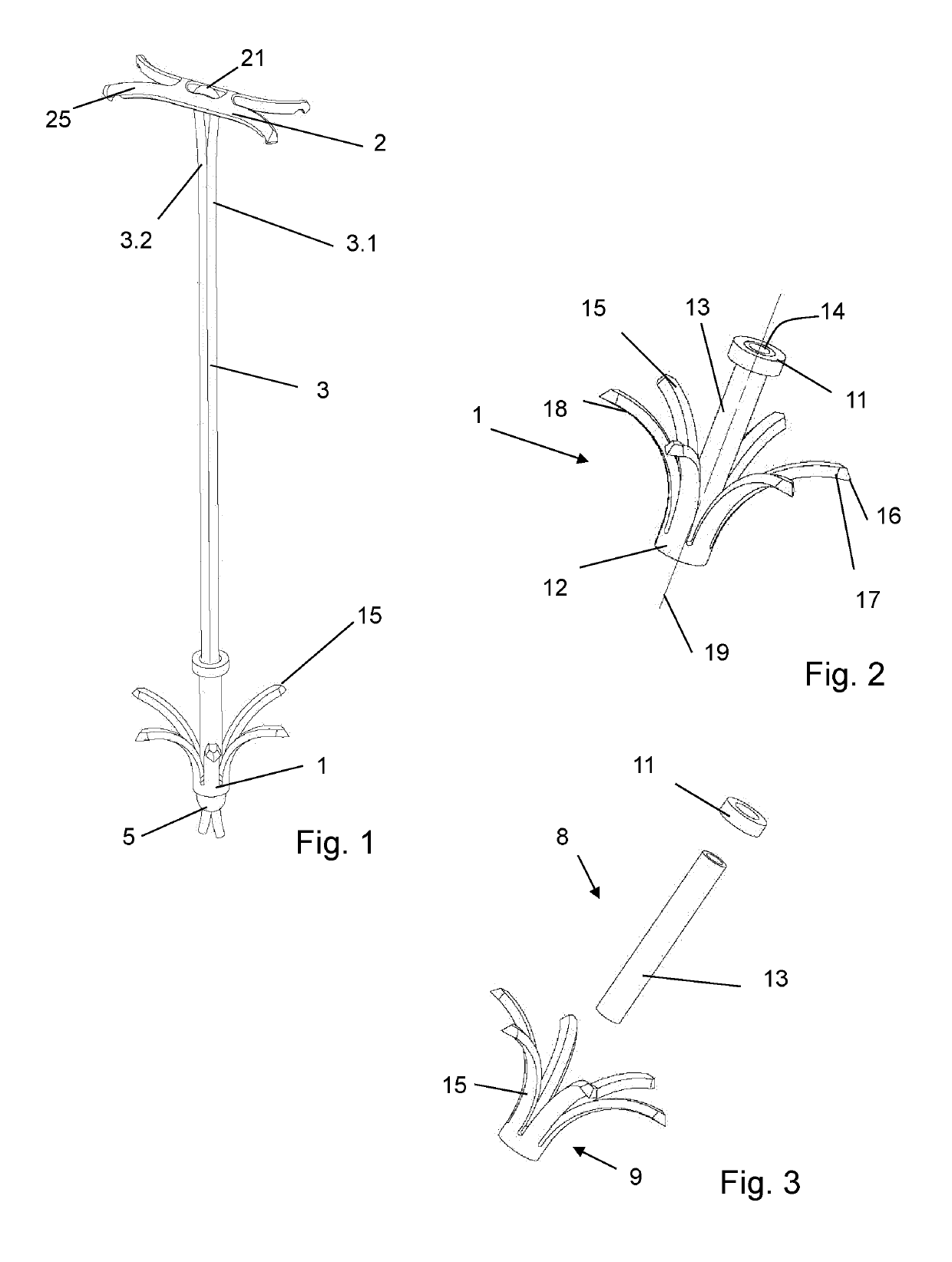
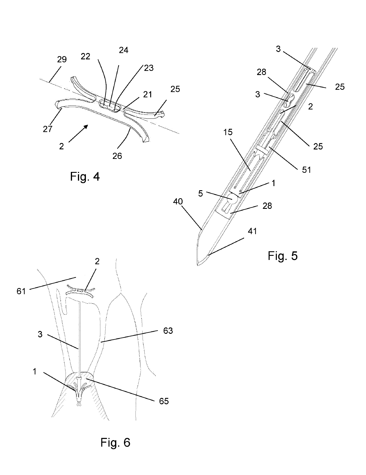
[0057]The implant illustrated in FIG. 1 includes a distal implant part 1, a proximal implant part 2 and a chord 3 connecting the proximal and distal implant parts. The chord 3 is guided from a distal end of the distal implant part 1 to the proximal implant part 2 and through the proximal implant part 2 back to the distal end of the distal implant part 2, so that the chord 3 is doubled and has two chord portions 3.1, 3.2 between the proximal and distal implant parts. Within the distal implant part 1 and between the distal and proximal ends thereof, the chord portions 3.1, 3.2 are guided in a shaft 13, and they are secured by a knot 5 distally of the distal implant part 1.

[0058]In FIGS. 2 and 3, the distal implant part 1 is shown in somewhat more detail. In the depicted embodiment, it is composed of a shaft piece 8 and a crown piece 9 as well as an optional collet piece 11. The shaft piece 8 acts as a stabilizer that helps orientating the distal implant part 1 in a longitudinal manner...


PUM


Abstract

A sutureless implant for replacing damaged natural chordae tedingeae of a human or possibly animal heart, the implant including a distal implant part, a proximal implant part, and an artificial chord. The distal implant part is configured to fit in a lumen of an implant delivery device and includes a self-spreading portion spreading radially outside when the distal implant part is released from the lumen, the self-spreading portion being capable of anchoring the distal implant part in human muscle tissue. The proximal implant part is configured to fit in the lumen of the implant delivery device and comprises a self-spreading portion spreading radially outside when the proximal implant part is released from the lumen, the self-spreading portion being capable of bearing on a tissue portion of leaflet tissue. The distal implant part and the proximal implant part are connected by the chord.

Description

BACKGROUND OF THE INVENTIONField of the Invention[0001]The invention is in the field of surgical, for example minimally invasive or interventional cardiology, devices for heart valve repair. It more particularly relates to an implant for repairing an atrioventricular heart valve, in particular the mitral heart valve or also the tricuspid heart valve, and to an according method.Description of Related Art[0002]Prolapses of a leaflet of the mitral valve into the left atrium and resulting valve insufficiency can cause serious dysfunctions of the heart. One reason for such prolapse is a damaging of the tendons (chordae tendineae) that connect the leaflets of the mitral valve to the papillary muscle through the left ventricle. Such damage may for example be a result of a myocardial infarction, tissue degeneration or infectious disease.[0003]A repair of such a prolapse demands the leaflet or leaflets to be re-connected to the papillary muscle, for example by synthetic fibres, such as Gore-...

Claims


Application Information

Patent Timeline
IPC IPC(8): A61F2/24A61B17/04
CPCA61F2/2457A61B17/0401A61F2/2466A61B2017/0409A61B2017/0417A61B2017/0458A61B2017/0464A61B2017/0437
Inventor SCHAFFNER, SILVIOAESCHLIMANN, TOBIASWUTHRICH, OLIVERBAUER, THOMAS
Owner COREMEDIC
Why Eureka
Try Eureka