Compact Interferometer Spectrometer

a technology of interferometer and spectrometer, which is applied in the field of compact interferometer, can solve the problems of limited array size and introduction of challenges, and achieve the effects of compact size and stability, the best filling area of the detector, and the quality of the interferogram

Active Publication Date: 2019-06-13
KEIT
View PDF2 Cites 2 Cited by
  • Summary
  • Abstract
  • Description
  • Claims
  • Application Information

AI Technical Summary

Benefits of technology

[0007]The present invention is directed to improvements in the interferometer described in the prior art. The folded-Sagnac geometry offers advantages in terms of compact size and stability ...

Problems solved by technology

The folded-Sagnac geometry offers advantages in terms of compact size and stability but introduces challenges in terms of how the area of the detector can be best filled and how the qu...

Method used


Image

  • Compact Interferometer Spectrometer
  • Compact Interferometer Spectrometer
  • Compact Interferometer Spectrometer

Examples


Embodiment Construction

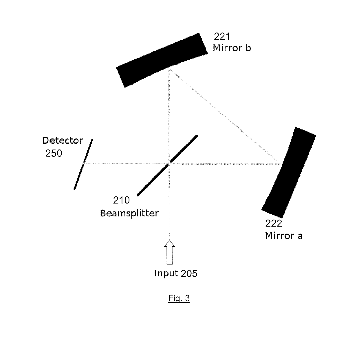
[0067]FIG. 3 shows an interferometer according to a Sagnac geometry. The interferometer comprises a detector 250 and optics for dividing a beam and guiding the resulting beam portions in opposing directions around a cyclic path.

[0068]The optics include a beamsplitter or other beam division optics 210, and two reflecting elements such as mirrors or mirror regions 221, 222. The beamsplitter 210 may be a partially reflecting mirror, a beamsplitter cube, a plate beamsplitter, etc. In one embodiment the beamsplitter may be a wedge beamsplitter having a partially reflecting surface. The mirror regions 221, 222 may be curved having the same curvature as each other or may have different curvatures. The curvature is so as to provide a concave mirror. The detector 250 is preferably a sensor with a pixel array.

[0069]If a beamsplitter is used it is preferably arranged at 45° to the angle of incidence of an input beam of light or radiation 205. The input beam is divided into two beam portions by...


PUM


Abstract

A common path interferometer is disclosed. The interferometer is arranged to divide an input beam into first and second beam portions directed in opposite directions around a cyclic path to form an interference pattern at a detector. The cyclic path is defined by at least two mirror regions curved in the plane of the cyclic path, such that the interference pattern represents path difference variations between the first and second beam portions. The interferometer further includes an input optic arranged in the beam path before division of the input beam into the beam portions. The input optic is configured to provide convergence to reduce the extent transversely to the plane of the cyclic path of the interference pattern at the detector. The beam and beam portions have different convergence requirements in the plane of, and transverse to the plane of, the cyclic path, which are addressed separately by the mirror regions and the input optic.

Description

FIELD OF THE INVENTION[0001]The present invention relates to a compact interferometer. The interferometer is a Fourier transform spectrometer and is configured based on Sagnac spectrometer geometry such that it may have no moving parts.BACKGROUND[0002]The most common design of Fourier transform interferometer is the Michelson interferometer. A Michelson interferometer, such as shown in FIG. 1, comprises a beamsplitter 10 and a pair of mirrors 21, 22. The beamsplitter 10 divides the light into two beam portions. The mirrors 21, 22 and beamsplitter 10 are arranged so that light passes along two linear paths, namely legs 31, 32. Each beam portion travels a return path along a different one of the legs. The optical path length along one of the legs 32 is adjustable. The beam portions recombine at a focal plane to form fringes 55. The beam portions may be focussed through a lens 40, arriving at the lens at equal angles of inclination. By displacing one of the reflecting mirrors 22 in the...

Claims


Application Information

Patent Timeline
IPC IPC(8): G01J3/453G01J3/02
CPCG01J3/4532G01J3/4531G01J3/0208G01J3/0256G01J3/453
Inventor STEPHENS, TIMOTHY JOHNSOBOL, JAMES PAUL
Owner KEIT
Why Eureka
Try Eureka