
Prelithiated and methods for prelithiating an energy storage device

a technology of energy storage device and prelithiation method, which is applied in the direction of active material electrodes, cell components, electrolytes, etc., can solve the problems of unreachable long-term cycling stability of high-si anodes paired with ncm or nca cathodes, and the instability of organic solvent-based electrolytes of batteries

Active Publication Date: 2019-06-13
ENEVATE CORP
View PDF0 Cites 33 Cited by
  • Summary
  • Abstract
  • Description
  • Claims
  • Application Information

AI Technical Summary

Benefits of technology

The patent text describes energy storage devices that use silicon-based electrodes, including prelithiated silicon active materials. The prelithiated materials have a high level of lithiation, which can be achieved by using a sacrificial lithium source. The energy storage devices also include a separator and electrolyte, and may contain a solid electrolyte interphase (SEI). The use of prelithiated silicon active materials can improve the performance and efficiency of energy storage devices.

Problems solved by technology

However, both Si-based anodes and high-voltage Ni rich NCM (or NCA) cathodes face formidable technological challenges, and long-term cycling stability with high-Si anodes paired with NCM or NCA cathodes has yet to be achieved.
However, especially in the first charge and within subsequent cycles, organic solvent based electrolytes of batteries are unstable and tend to decompose a portion of the Li content to form a solid electrolyte interphase (SEI).
As a result of cycling, the Li losses gradually accumulate in the subsequent cycles and causes performance (capacity) fade.

Method used


Image

  • Prelithiated and methods for prelithiating an energy storage device
  • Prelithiated and methods for prelithiating an energy storage device
  • Prelithiated and methods for prelithiating an energy storage device

Examples


example 1

le Coulombic Efficiency

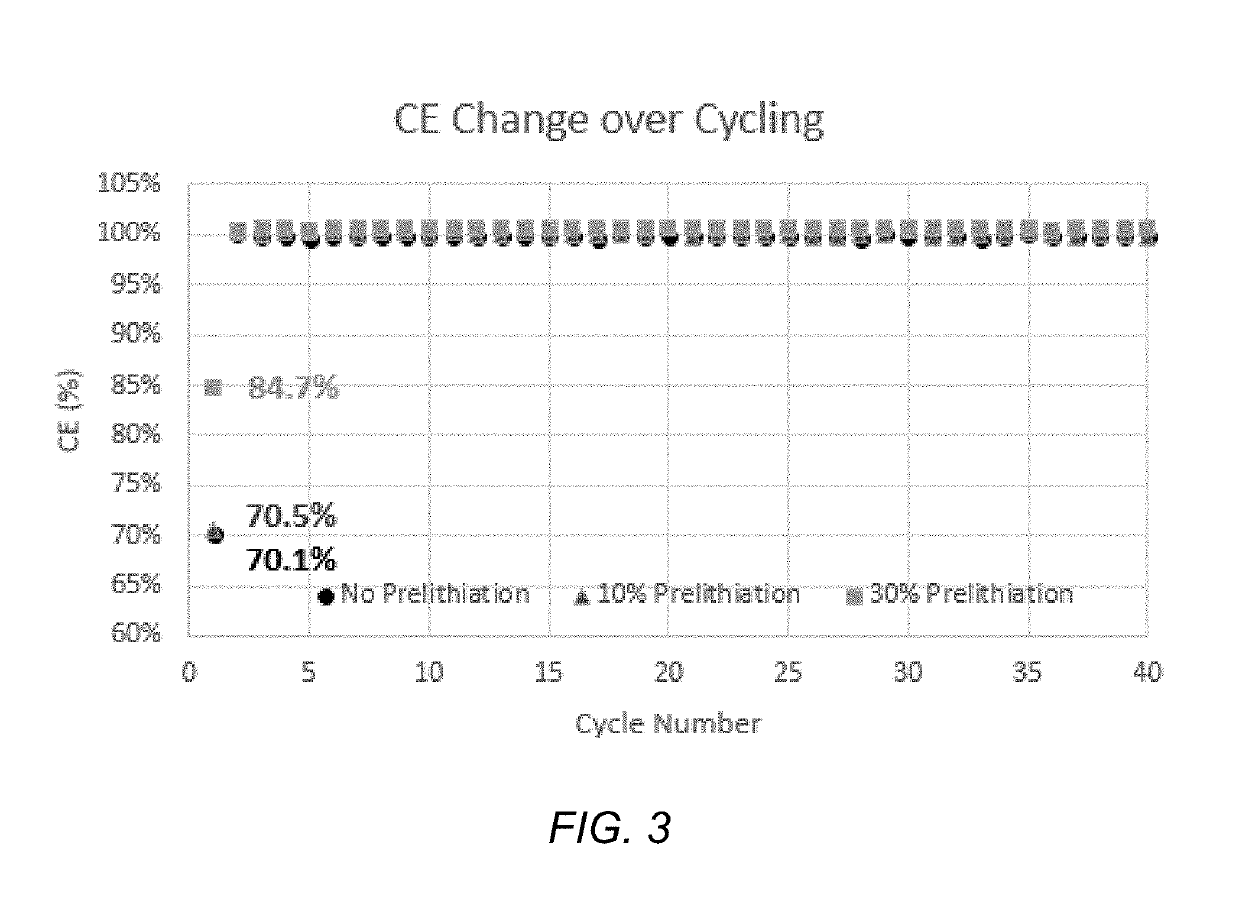
[0075]FIG. 3 demonstrates the effects of prelithiation of a silicon dominated anode has on the change of first cycle coulombic efficiency (CE) over cycles in full cell format. The first cycle CE of the control device was 70.1% due to a large portion of Li required for the SEI formation. Control devices were not able to achieve a perfect CE, and their CE's decreased from 99.9% to 99.7% within the initial 40 cycles.

[0076]In contrast, the first cycle capacity loss was less for the prelithiated anode cells. The first cycle CE was 70.5% for a device with a 10% prelithiated anode, and 84.7% for a device with a 30% prelithiated anode. In addition, the prelithiated silicon dominated anode cells were able to achieve a perfect cycle CE of >100%.

example 2

tability

[0077]FIG. 4 demonstrates the cycling stability of the prelithiated silicon dominated anodes when tested at C / 20 for 40 cycles. The capacity retention after 40 cycles was 105.2% for a device with a 10% prelithiated anode, and 100.2% for a device with a 30% prelithiated anode. In contrast, the control device showed a steady capacity fade of 93.6% over 40 cycles.

example 3

erformance

[0078]FIG. 5 shows cycling performance of battery cells containing prelithiated silicon with 0%, 10%, 20% and 30% prelithiation. FIG. 5 demonstrates a marked improvement in cycling capacity of prelithiated structures when compared to controls, and points to a systemic method of determining the optimal prelithiation content.


PUM


Abstract

The present disclosure relates to prelithiated Si electrodes, methods of prelithiating Si electrodes, and use of prelithiated electrodes in electrochemical devices are described. There are several characteristics of electrode prelithiation that enable the superior battery performance. First, a prelithiated silicon anode is already in its expanded state during SEI formation, and therefore less of the SEI layer breaks down and reforms during cycling. Second, the prelithiated anode has a lower anode potential, which may also help the cycle performance of an electrochemical device.

Description

PRIORITY CLAIM[0001]This application claims the benefit of priority under 35 U.S.C. §119(e) of U.S. Provisional application No. 62 / 596,053 filed on Dec. 7, 2017. The entire disclosure of each of these priority documents is incorporated herein by reference.BACKGROUNDField[0002]The present application relates generally to prelithiation of an energy storage devices. In particular, the present application relates to prelithiation compositions and methods for use in lithium-ion energy storage devices with silicon-based anode materials.Description of the Related Art[0003]As the demands for both zero-emission electric vehicles and grid-based energy storage systems increase, lower costs and improvements in energy density, power density, and safety of lithium (Li)-ion batteries are highly desirable. Enabling the high energy density and safety of Li-ion batteries requires the development of high-capacity, and high-voltage cathodes, high-capacity anodes and accordingly prelithiated electrodes....

Claims


Application Information

Patent Timeline
IPC IPC(8): H01M4/38H01M10/0525H01M4/36H01M4/587H01M10/0569
CPCH01M4/386H01M10/0525H01M4/364H01M4/587H01M10/0569H01M2300/0034H01M2004/027H01M4/0445H01M4/134Y02E60/10
Inventor PARK, BENJAMIN YONGBONHOMME, FREDERICTENG, SHIANG JENHOUSE, VICTOR E.
Owner ENEVATE CORP
Learn More