Supercharge Your Innovation With Domain-Expert AI Agents!

Power supply system for vehicle, and control method of power supply system

a power supply system and vehicle technology, applied in the direction of battery/fuel cell control arrangement, battery/cell propulsion, transportation and packaging, etc., can solve the problem of time lag caused by delay, main relay cannot be closed, abnormality of bidirectional converter detection, etc., to avoid time lag

Active Publication Date: 2019-06-13
TOYOTA JIDOSHA KK
View PDF0 Cites 2 Cited by
  • Summary
  • Abstract
  • Description
  • Claims
  • Application Information

AI Technical Summary

Benefits of technology

The patent text describes a technical solution to prevent overheating and delays in starting up a vehicle after a main switch is turned on while the temperature of a bidirectional converter is high. The solution involves stopping the cooler that cools the bidirectional converter and retaining it in a high temperature state for a while before starting up the vehicle. This helps to avoid precharging issues and ensures that the vehicle can be quickly put in a travelable state after the main switch is turned on.

Problems solved by technology

In that case, precharging is not executable for a while after the main switch is turned on, and therefore the system main relay cannot be closed.
Therefore, a time lag caused by a delay in the start of precharging is not generated before the vehicle is put in the travelable state after the main switch is turned on.
With this configuration, whenever the main switch of the vehicle is turned off, abnormality of the bidirectional converter is detectable.

Method used


Image

  • Power supply system for vehicle, and control method of power supply system
  • Power supply system for vehicle, and control method of power supply system
  • Power supply system for vehicle, and control method of power supply system

Examples


Embodiment Construction

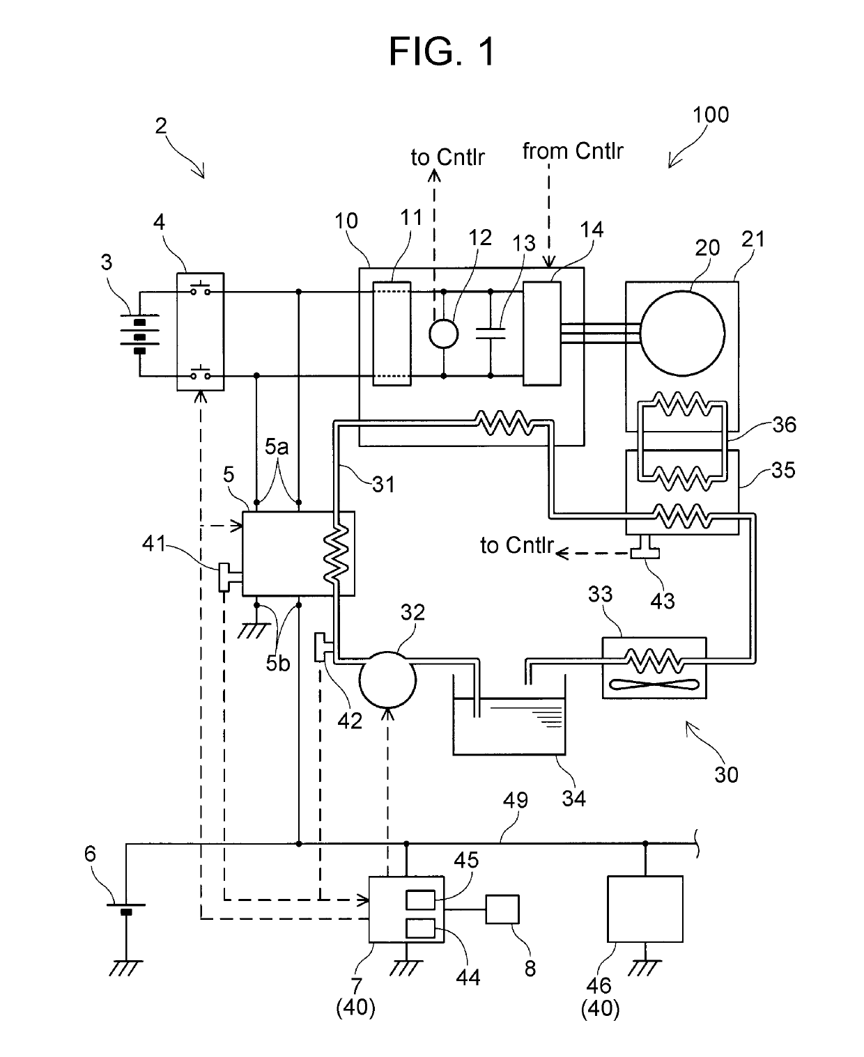
[0019]A power supply system 2 of an embodiment will be described with reference to the drawings. The power supply system 2 of the embodiment is mounted on an electric vehicle 100. FIG. 1 illustrates a block diagram of an electric power system of the electric vehicle 100 including the power supply system 2. In FIG. 1, broken arrow lines represent signal lines. A character string “to Cntlr” means “to a controller 7 (to Controller)”. A character string “from Cntlr” means “from the controller 7 (from Controller)”. Solid lines connecting devices represent transfer routes of electric power. The electric vehicle 100 of the embodiment includes the power supply system 2, a traveling motor 20, and a main switch8. The electric vehicle 100 travels with the motor 20.

[0020]The power supply system 2 includes a main battery 3, a system main relay 4, a sub-battery 6, an electric power converter 10, a bidirectional converter 5, the controller 7, and a cooler 30. The power supply system 2 supplies dri...


PUM


Abstract

A power supply system for a vehicle includes a main power supply, an electric power converter including a capacitor, a relay, a sub power supply, a bidirectional converter, and a controller. The controller is configured to cause the sub power supply and the bidirectional converter to precharge the capacitor when a main switch of the vehicle is turned on, such that the sub power supply and the bidirectional converter to precharge the capacitor before the relay is closed to connect the electric power converter to the main power supply. When the temperature of the bidirectional converter is higher a specified temperature threshold and the main switch is turned off, the controller is configured to retain the relay in a closed state for a specified time and then open the relay to separate the electric power converter from the main power supply.

Description

INCORPORATION BY REFERENCE[0001]The disclosure of Japanese Patent Application No. 2017-238245 filed on Dec. 13, 2017 including the specification, drawings and abstract is incorporated herein by reference in its entirety.BACKGROUND1. Technical Field[0002]The present specification discloses a technique relating to a power supply system mounted on a vehicle, and a control method of the power supply system. The present specification particularly relates to a power supply system mounted on an electric vehicle to supply drive electric power to a traveling motor. In the present specification, the term “electric vehicle” includes a hybrid vehicle including both a motor and an engine, and a vehicle having a fuel cell as a power supply.2. Description of Related Art[0003]Electric vehicles are mounted with a power supply system that supplies drive electric power to a traveling motor. For example, such a power supply system is disclosed in Japanese Patent Application Publication No. 2017-085869 ...

Claims


Application Information

Patent Timeline
IPC IPC(8): H02H7/122H02P27/06H02J7/00B60L11/18
CPCH02H7/122H02P27/06B60L50/50H02J7/345H02J7/0052B60L2210/42B60L1/02B60L58/20H02P29/68H02H5/04Y02T10/64Y02T10/72Y02T10/70Y02T90/14Y02T10/7072H02J7/00
Inventor NOZAWA, TAKASHI
Owner TOYOTA JIDOSHA KK
Features
  • R&D
  • Intellectual Property
  • Life Sciences
  • Materials
  • Tech Scout
  • Unparalleled Data Quality
  • Higher Quality Content
  • 60% Fewer Hallucinations
Learn More