Method and apparatus for performing random access in wireless communication system supporting beamforming

a wireless communication system and random access technology, applied in the direction of electrical equipment, radio transmission, transmission, etc., can solve the problem that the directional beam-based transmission cannot transmit or receive a signal, and achieve the effect of reducing unnecessary overhead, simple procedure, and increasing transmission rang

Inactive Publication Date: 2019-06-13
SAMSUNG ELECTRONICS CO LTD
View PDF2 Cites 40 Cited by
  • Summary
  • Abstract
  • Description
  • Claims
  • Application Information

AI Technical Summary

Benefits of technology

[0017]According to an embodiment of the present disclosure, even when each user equipment (UE) supports a beam with a different width, it is possible to adjust beam width using a simple procedure. Further, when the width of a transmission beam is updated by the adaptive determination of beam width, a signal transmitted by a UE becomes strong, thus increasing a transmission range.
[0018]In addition, according to another embodiment of the present disclosure, a UE can variably set the reception of a response to a preamble transmitted for random access depending on the conditions of a system and may then perform communication using an optimal beam among a plurality of beams, thus reducing unnecessary overhead.
[0019]Further, according to still another embodiment of the present disclosure, when a next-generation mobile communication system supports dual connectivity between a base station of an LTE system and a base station of an NR system, it is possible to efficiently configure and transmit a new PHR format supporting different radio access technologies (RATs), thus enabling a user to receive a high-quality and high-capacity service.

Problems solved by technology

However, since it is difficult to secure an ultra-wideband frequency of 100 MHz or more in the frequency band of hundreds of MHz or several GHz used for LTE and LTE-A, the NR system considers a method for transmitting a signal using a wide frequency band existing in a frequency band of 6 GHz or more.
However, directional beam-based transmission cannot transmit or receive a signal at a position where no beam is formed.

Method used


Image

  • Method and apparatus for performing random access in wireless communication system supporting beamforming
  • Method and apparatus for performing random access in wireless communication system supporting beamforming
  • Method and apparatus for performing random access in wireless communication system supporting beamforming

Examples


first embodiment

[0066]In describing the present disclosure below, a detailed description of related known configurations or functions incorporated herein will be omitted when it is determined that the detailed description thereof may unnecessarily obscure the subject matter of the present disclosure. Hereinafter, embodiments of the present disclosure will be described with reference to the accompanying drawings.

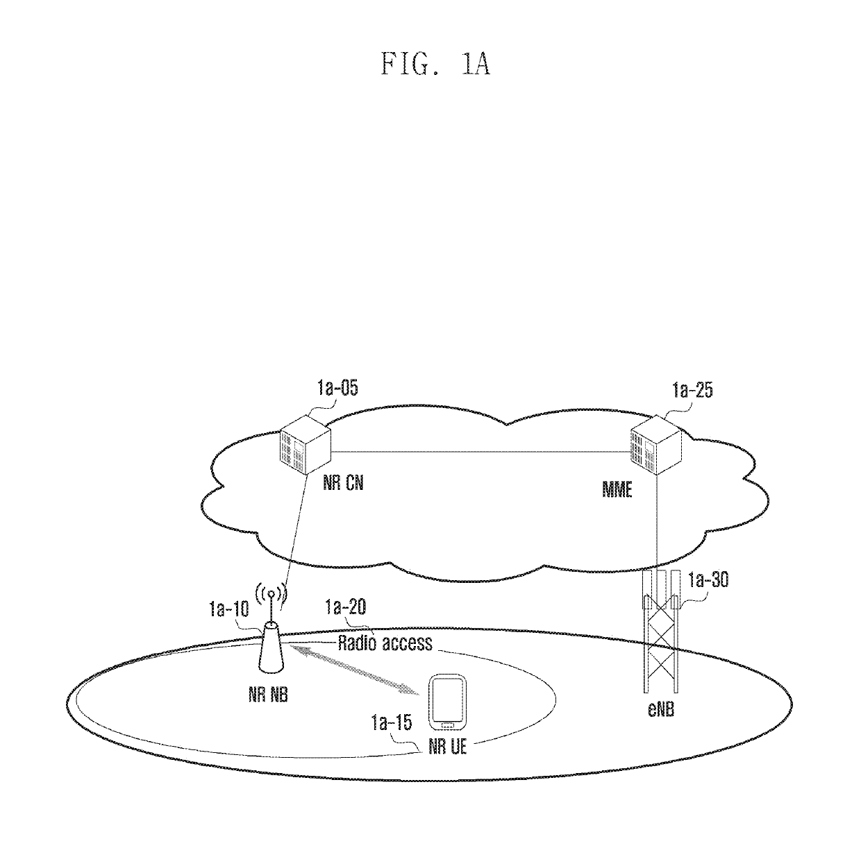
[0067]FIG. 1A illustrates the structure of a next-generation mobile communication system.

[0068]Referring to FIG. 1A, a radio access network of the next-generation mobile communication system includes a new radio Node B (hereinafter, “NR NB”) 1a-10 and a new radio core network (NR CN) 1a-05. A new radio user equipment (hereinafter, “NR UE” or “UE”) 1a-15 accesses an external network through the NR NB 1a-10 and the NR CN 1a-05.

[0069]In FIG. 1A, the NR NB 1a-10 corresponds to an evolved Node B (eNB) of an existing LTE system. The NR NB is connected to the NR UE 1a-15 via a radio channel and may...

embodiment 2

[0199]FIG. 3A illustrates the structure of a next-generation mobile communication system according to the present disclosure.

[0200]Referring to FIG. 3A, a cell served by an NR Node B (NR NB) 3a-05 operating on the basis of a beam may include a plurality of transmission reception points (TRPs) 3a-10, 3a-15, 3a-20, 3a-25, 3a-30, 3a-35, and 3a-40.

[0201]The TRPs 3a-10 to 3a-40 are blocks resulting from the separation of only a function of transmitting and receiving a physical signal from an existing LTE base station (eNB) and may include a plurality of antennas. Particularly, the TRPs 3a-10 to 3a-40 may perform beamforming by generating beams in different directions using a plurality of transmission and reception antennas and may also be referred to as a beam group (BG).

[0202]A UE 3a-50 accesses the NR NB 3a-05 and an external network through the TRPs 3a-10 to 3a-40. To serve traffic for users, the NR NB 3a-05 performs scheduling by collecting state information on UEs, such as a buffer ...

third embodiment

[0286]FIG. 4A illustrates the structure of an LTE system for reference to describe the present disclosure.

[0287]Referring to FIG. 4A, the wireless communication system includes a plurality of base stations 4a-05, 4a-10, 4a-15, and 4a-20, a mobility management entity (MME) 4a-25, and a serving-gateway (S-GW) 4a-30. A user equipment (hereinafter, “UE” or “terminal”) 4a-35 is connected to an external network through the base stations 4a-05, 4a-10, 4a-15, and 4a-20 and the S-GW 4a-30.

[0288]The base stations 4a-05, 4a-10, 4a-15, and 4a-20 are access nodes of a cellular network and provide wireless connection for UEs connected to the network. That is, in order to serve traffic of users, the base stations 4a-05, 4a-10, 4a-15, and 4a-20 performs scheduling by collecting state information on UEs, such as a buffer state, an available transmission power state, and a channel state and supports connection between the UEs and a core network (CN).

[0289]The MME 4a-25 is a device that performs not o...


PUM


Abstract

The present disclosure relates to a communication technique for converging an IoT technology with a 5G communication system for supporting a higher data transmission rate beyond a 4G system, and a system therefor. The present disclosure may be applied to an intelligent service (for example, a smart home, a smart building, a smart city, a smart car or connected car, healthcare, digital education, retail business, a security and safety related service, or the like) on the basis of a 5G communication technology and an IoT related technology. The present invention provides a method for performing random access by a terminal in a wireless communication system supporting beamforming, the method comprising the steps of: receiving, from a base station, uplink resource information for transmitting a preamble and random access response (RAR) information corresponding to the resource information; determining, on the basis of the uplink resource information, a resource for transmitting at least one preamble through beam sweeping; and transmitting the at least one preamble to the base station through the beam sweeping.

Description

TECHNICAL FIELD[0001]The present disclosure relates to a method and an apparatus for efficiently performing random access in a wireless communication system supporting beamforming.BACKGROUND ART[0002]In order to meet the demand for wireless data traffic, which has been increasing since the commercialization of a 4G communication system, efforts are being made to develop an improved 5G communication system or pre-5G communication system. For this reason, a 5G communication system or pre-5G communication system is referred to as a beyond-4G-network communication system or a post-LTE system. To achieve a high data transmission rate, implementing a 5G communication system in an extremely high frequency (mmWave) band (for example, a 60 GHz band) is being considered. To relieve the path loss of radio signals and to increase the transmission distance of radio signals in an extremely high frequency band, beamforming, massive multiple-input and multiple-output (massive MIMO), full dimensiona...

Claims


Application Information

Patent Timeline
Patent Type & Authority Applications(United States)
IPC IPC(8): H04W16/28H04W72/04
CPCH04W16/28H04W72/0413H04W74/00H04W74/08H04W74/0833H04W72/046H04B7/0695H04W74/002H04W72/21
Inventor KIM, SOENGHUNJIN, SEUNGRIKIM, DONGGUNKIM, SANGBUMJANG, JAEHYUKSAYENKO, ALEXANDER
Owner SAMSUNG ELECTRONICS CO LTD
Why Eureka
Try Eureka