Data transmitter/receiver

a data transmitter and receiver technology, applied in transmission systems, fibre transmission, transmission, etc., can solve the problems of noticeably limited transmission range of optical data transmission, low optical transmitting and receiving power, etc., to increase the transmission certainty and transmission range, the effect of large apertures

Inactive Publication Date: 2002-07-09
VISHAY SEMICON
View PDF3 Cites 16 Cited by
  • Summary
  • Abstract
  • Description
  • Claims
  • Application Information

AI Technical Summary

Benefits of technology

to substantially increase the optical transmission and reception power for wireless optical transceivers operating with electromagnetic waves in the range of infrared to and including ultraviolet;
to construct the present transceiver, especially its housing, in such a way that a substantially larger lens aperture can be realized without requiring a larger housing for accommodating a larger lens or lenses;
to increase the lens diameter for an enlarged aperture and a correspondingly increased transmission and reception range while simultaneously optimally reducing the dimensions of a housing carrying the lens or lenses.
The advantages of the present transceiver are seen in that the positioning of the hemisphere or sphere permits substantially larger apertures for the lenses which are positioned in front of the emitter chip and in front of the detector chip. Larger lenses permit increasing the optical transmitter power and the optical receiver power which has the advantage that the transmission certainty and the transmission range are substantially increased compared to conventional transceivers. Due to the component arrangement according to the invention, the first housing section can have a flat parallelepiped shape which permits a symmetric arrangement of the terminals that define the above mentioned mounting plane, whereby the insertion of circuit elements and chips by an insertion automat is facilitated. The size of the present transceiver corresponds approximately to the size of an SO-8 housing (small outline with eight terminals). Yet, the transmission range is increased by a factor that is proportional to the square of the lens aperture surface sizes gained by the invention compared to the conventional lens aperture sizes in a housing of the same size as the present housing, Thus, no special housings are necessary for achieving the improved transmission range with the present transceiver.

Problems solved by technology

For example, due to the small apertures of the lenses that are arranged in front of the detector chip and in front of the emitter chip, the optical transmitting and receiving power is rather low, whereby the transmission range of the optical data transmission is noticeably limited.

Method used


Image

  • Data transmitter/receiver
  • Data transmitter/receiver
  • Data transmitter/receiver

Examples


Embodiment Construction

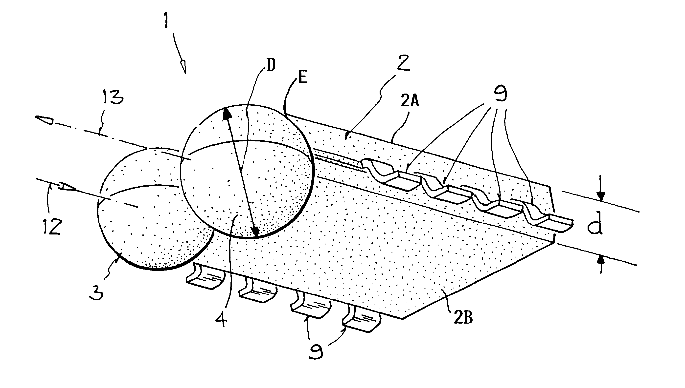
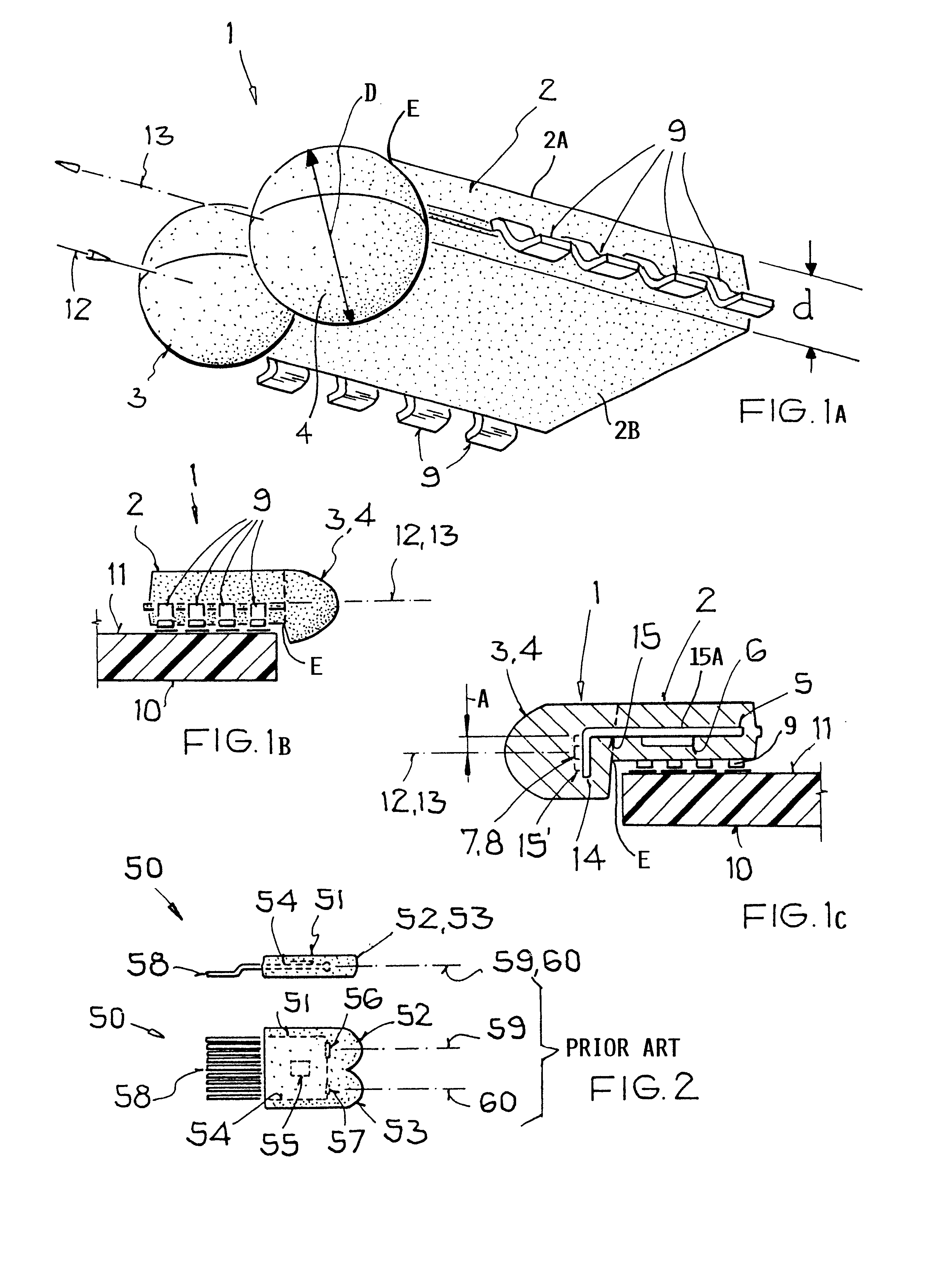
FIGS. 1A, 1B and 1C illustrate a transceiver 1 for directed, bi-directional, optical, wireless data transmissions by means of electrical and optical data signals. The transceiver is constructed for a side view mode. The transceiver 1 includes an elongated first flat housing section 2 having a parallelepiped shape and at least one second housing section 3, preferably two second housing sections 3 and 4, having a spherical configuration arranged laterally along one side wall or edge E of the flat housing section 2. The flat first section 2 has a thickness d between its parallel surfaces 2A and 2B. The spherical second sections have a diameter D.

The arrangement shown is referred to as a side view mode because the radiation wave energy enters and leaves the transceiver 1 laterally as symbolized by optical, directional axes 12 and 13. The housing section 2 is made of a known potting mass and comprises an electrically conducting strip 5 preferably forming a grid carrier or support or moun...


PUM


Abstract

A transceiver, especially an infrared transceiver, has a flat surface section and at least one or two lens forming housing sections integrally formed with the flat housing section. The lens housing sections are positioned so that one flat surface of the flat housing extends tangentially to the lens housing section or sections while the latter project outside the opposite flat housing surface. The lens housing section or sections are positioned along an edge of the flat housing section. For this purpose the lens forming housing section or sections have a substantially larger diameter (D) than the thickness (d) of the flat housing section. The respective lenses thus may have a substantially larger aperture, thereby increasing the wireless transmission and reception range of optical data transmission signals, in accordance with IRDA standards.

Description

PRIORITY CLAIMThis application is based on and claims the priority under 35 U.S.C. .sctn.119 of German Patent Application 198 08 004.2, filed on Feb. 26, 1998, the entire disclosure of which is incorporated herein by reference.The invention relates to a structural component forming a transmitter and a receiver for a bi-directional, wireless transmission of data carried by radiation energy particularly in the range of infrared radiation to and including ultraviolet radiation.BACKGROUND INFORMATIONSuch transceivers are currently used for data transmissions particularly with an infrared radiation carrier for which IRDA standards have been developed. The data transmission takes place optically from one point to another in accordance with the just mentioned standards, for example for remote controlled purposes. The firm Temic Semiconductor GmbH of Heilbronn, Germany markets such transceivers as Models TFDS 4000 or TFDS 6000 for various purposes. These transceivers have integrated compone...

Claims


Application Information

Patent Timeline
Patent Type & Authority Patents(United States)
IPC IPC(8): H01L31/0203H01L31/0232H04B10/24H04B10/25G08C23/04
CPCH01L31/0203H01L31/0232H04B10/2503H01L2924/1815H01L31/02325H04B10/2589
Inventor KRIEGER, JOCHEN
Owner VISHAY SEMICON
Why Eureka
Try Eureka