Suction catheter systems for applying effective aspiration in remote vessels, especially cerebral arteries

a technology of suction catheter and remote vessel, applied in the field of catheters, can solve the problems of increasing the difficulty of reaching target locations in these vessels, affecting the effect of suction catheter system, and blocking small distal vessels

Active Publication Date: 2019-06-20
MIVI NEUROSCI INC
View PDF22 Cites 12 Cited by
  • Summary
  • Abstract
  • Description
  • Claims
  • Application Information

AI Technical Summary

Benefits of technology

[0005]In a first aspect, the invention pertains to a method for removing thrombus from a patient's vessel using a suction catheter system comprising: proximal fittings comprising a hemostatic valve; a guide catheter with a distal end and a proximal end connected to the proximal fittings; and a suction extension comprising a tubular extension with a distal end and a proximal end, a connecting section at the proximal end of tubular extension, and a control structure extending in a proximal direction from the tubular extension. The method can comprise delivering suction through a suction lumen extending from the distal end of the tubular extension to the proximal end of the guide catheter with the distal end of the tubular extension extending from the distal end of the guide catheter. Generally, for at least a portion of the time of delivery of suction, the connecting section is within the guide catheter, and the control structure extends from the proximal end of the guide catheter. The method can also comprise withdrawing the tubular extension from the guide catheter lumen during delivery of negative pressure in the suction lumen from the proximal fittings, in which the connecting section is withdrawn into the proximal fittings distal to the hemostatic valve such that a suction lumen then extends fully along a lumen of the guide catheter.
[0006]In a further aspect, the invention pertains to a suction catheter system comprising a guide catheter having a tubular shaft with a central lumen having, a proximal end and a distal opening, a suction extension, and proximal fittings. The suction extension can comprise a connecting section with a central lumen, a tubular extension, and a control structure. The tubular extension can comprise a tube that is connected with the connecting section and extends from the connecting section in a distal direction to form a continuous lumen through the central lumen of the connecting section through the tube of the tubular extension, and the control structure can comprise an elongated structure extending from the connecting section in a proximal direction. The connecting section can be configured to slide within at least a portion of the central lumen of the guide catheter to change the relative position of the connecting section within the central lumen and provide for at least a portion of tubular extension to extend outward from the distal opening of the tubular shaft at appropriate configurations of the connecting section. The proximal fittings generally can be connected to the proximal end of the guide catheter and can comprise a branched manifold with at least one branch having a hemostatic valve and a tubular segment to provide a length between the hemostatic valve and the proximal end of the tubular shaft of the guide catheter that is at least as long as the length of the tube of the suction extension.
[0007]In another aspect, the invention pertains to a suction catheter system comprising a guide catheter comprising a tubular shaft with a central lumen, and having a proximal end and a distal opening, a suction extension, and proximal fittings. The suction extension can comprise a connecting section with a central lumen, a tubular extension, and a control structure. The tubular extension can comprise a tube that is connected with the connecting section and extends from the connecting section in a distal direction, and the control structure can comprise an elongated structure extending from the connecting section in a proximal direction. Generally, the connecting section can be configured to slide within at least a portion of the central lumen of the guide catheter to change the relative position of the connecting section within the central lumen and to provide for at least a portion of tubular extension to extend outward from the distal opening of the tubular shaft at appropriate configurations of the connecting section. The proximal fittings can comprise a branched manifold with at least one branch having a hemostatic valve, and with a pressure sensor configured to measure the pressure in the proximal fittings. Generally, the proximal fittings are connected to the proximal end of the guide catheter.
[0008]In an additional aspect, the invention pertains to a method for removing thrombus from a patient's vessel using a suction catheter system comprising proximal fittings comprising a hemostatic valve and a pressure sensor configured to measure the pressure in the proximal fittings; a guide catheter with a distal end and a proximal end connected to the proximal fittings; and a section extension. The suction extension can comprise a tubular extension with a distal end, a connecting section at the proximal end of tubular extension, and a control structure extending in a proximal direction from the ...

Problems solved by technology

Blood vessels in the brain follow particularly tortuous paths which can increase the difficulty of reaching target locations in these vessels.
Other vessels in a patient can also follow winding paths that increase the difficulty of reaching target locations.
Furthermo...

Method used


Image

  • Suction catheter systems for applying effective aspiration in remote vessels, especially cerebral arteries
  • Suction catheter systems for applying effective aspiration in remote vessels, especially cerebral arteries
  • Suction catheter systems for applying effective aspiration in remote vessels, especially cerebral arteries

Examples


Embodiment Construction

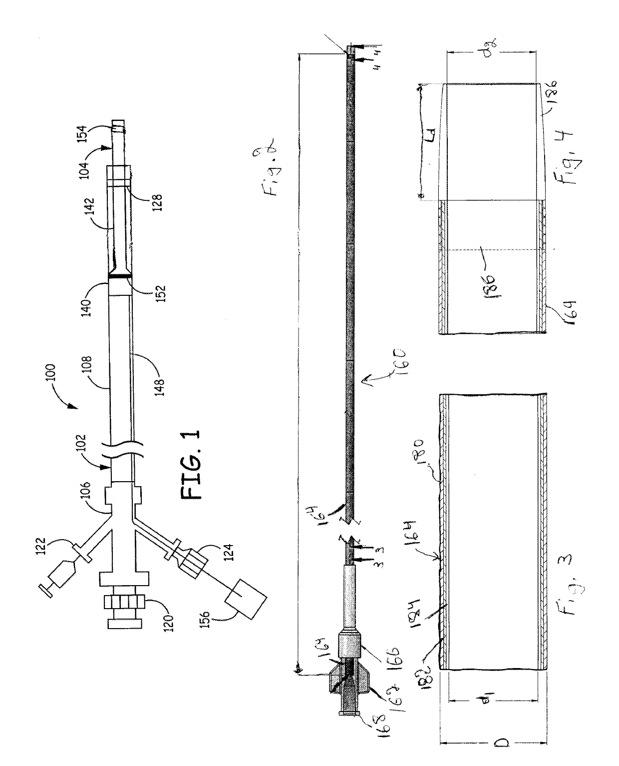
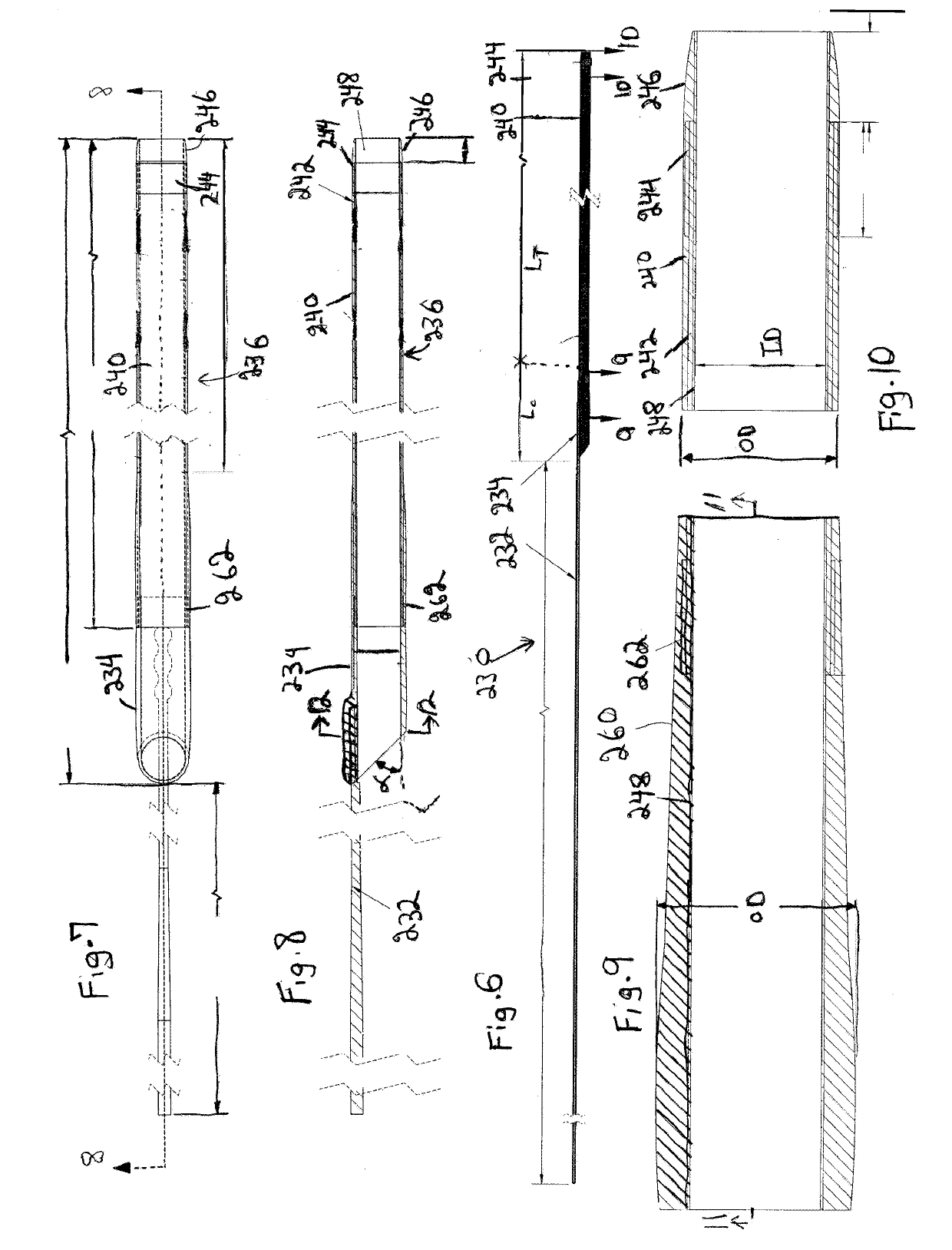
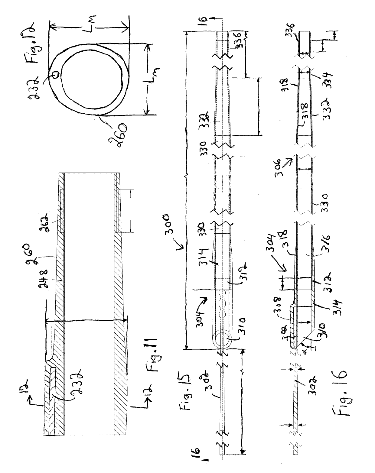
[0051]A suction catheter system can include a guide catheter adapted with a suction extension having a narrower distal tube that can provide suction with a high flow rate. In some embodiments, the suction extension has a connecting section that has an asymmetric circumference interfacing with the inner surface of the guide catheter with contact at two locations to provide an effective fluid seal while providing for translation of the suction extension within the guide catheter. In alternative or additional embodiments, the guide catheter can have a distal portion of a tubular element that has a narrower diameter that effectively limits the movement of the suction extension in a distal direction. Proximal fittings can be provided in some embodiments to allow withdrawal of the tubular portion (tubular extension) of the suction extension from the guide catheter without bringing the tubular extension of the suction extension through a hemostatic valve. Methods are described for the use ...


PUM


Abstract

A suction catheter system is described with a suction extension interfaced with a guide catheter to form a continuous suction lumen extending through a portion of the guide catheter and through the suction extension. The suction extension can be positioned by tracking the suction nozzle through a vessel while moving a proximal portion of the suction extension within the lumen of the guide catheter. The suction extension can comprise a connecting section with a non-circular cross section for interfacing with the inner lumen of an engagement section of the guide catheter. The tubular body of the guide catheter can have a reduced diameter distal section the can be useful to restrain the movement of the suction extension. Proximal fittings attached to the guide catheter can facilitate safe removal of the catheter system from the patient by allowing for the removal of some or all of a tubular extension of the suction extension from the guide catheter behind a hemostatic seal. Pressure sensors connected to the proximal fittings can help to guide the procedures with reduced risk of embolizing thrombus.

Description

FIELD OF THE INVENTION[0001]The invention relates to catheters designed for use in bodily vessels with tortuous paths, such as cerebral arteries. In particular, the invention relates to suction catheter systems comprising a guide catheter and a suction extension slidably disposed within the guide catheter.BACKGROUND OF THE INVENTION[0002]Procedures in blood vessels of the brain are gaining use as an approach for ameliorating acute stroke events or other interventions in blood vessels in the brain. Blood vessels in the brain follow particularly tortuous paths which can increase the difficulty of reaching target locations in these vessels. Other vessels in a patient can also follow winding paths that increase the difficulty of reaching target locations.[0003]Aspiration catheters have found use with respect to removal of clots from vessels. Furthermore, a significant reason for ischemic injury during percutaneous procedures can be generation of emboli that block smaller distal vessels....

Claims


Application Information

Patent Timeline
IPC IPC(8): A61B17/22A61M1/00A61M25/00
CPCA61B17/22A61M1/008A61M25/0068A61M25/0074A61B2017/22079A61B2217/005A61M25/10A61M25/09A61B17/00234A61B17/221A61B2017/00331A61B2017/2212A61B2017/320716A61B2090/064A61F2/013A61M1/74A61M1/84A61M25/0668A61M2205/3344A61M2210/0693A61M1/732A61M1/85A61M39/10A61M1/00A61M27/006A61M1/71
Inventor OGLE, MATTHEW F.
Owner MIVI NEUROSCI INC
Why Eureka
Try Eureka