
Fabrication of High-Temperature Superconducting Striated Tape Combinations

a technology of striated tape and superconducting hts, which is applied in the direction of superconductor devices, permanent superconductor devices, and solvents, etc., can solve the problems of significant losses in ac applications, bottlenecks in the development of inductors, transformers, and stators for motors and generators, and inability to demonstrate a practical transposed multifilament twisted hts coated conductor with low ac losses. achiev

Active Publication Date: 2019-06-20
UNITED STATES OF AMERICA
View PDF1 Cites 0 Cited by
  • Summary
  • Abstract
  • Description
  • Claims
  • Application Information

AI Technical Summary

Benefits of technology

This patent describes a way to make a single, integrated tape structure by aligning and bonding two high-temperature superconducting tapes. An insulating layer reinforces the adhesion between the tapes, reducing mechanical stress at the electrical connections. This method is suitable for a reel-to-reel production process. Overall, this disclosure presents a more efficient and scalable way to create a high-temperature superconducting tape structure.

Problems solved by technology

Different types of cables and wires that use 2G HTS are being developed for high current applications but the flat geometry causes significant losses in AC applications.
The lack of conductors and cables suitable for AC applications has created a bottleneck that complicates the development of inductors, transformers, and stators for motors and generators.
There has been no demonstration of a practical transposed multifilament twisted HTS coated conductor with low AC losses.
There are several technical challenges associated with these prior art methods.
First, in all cases the integrity of the bond relies on the mechanical strength of the electrical connection for adhesion.
Second, the time required for diffusion bonding prevents practical scale-up of the fabrication.
Third, the insulating layer creates a gap between the tapes that complicates the electrical bonding process.
Fourth, the insulating layers previously used do not provide adequate isolation of adjacent filaments during solder bonding.

Method used


Image

  • Fabrication of High-Temperature Superconducting Striated Tape Combinations
  • Fabrication of High-Temperature Superconducting Striated Tape Combinations

Examples


example 1

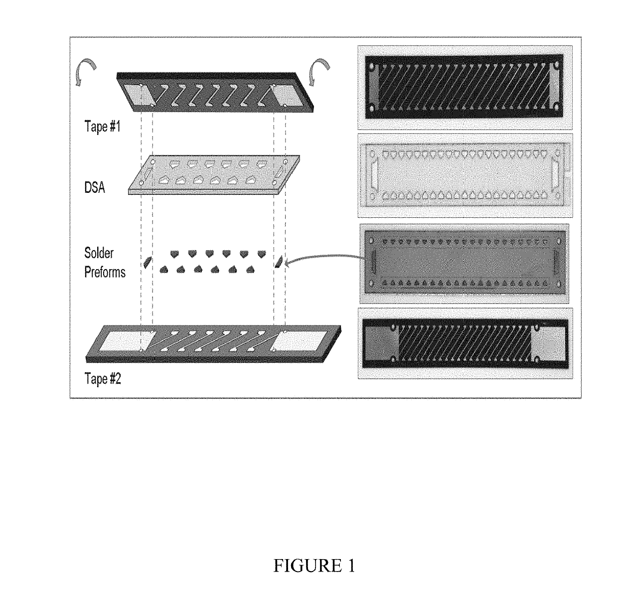
[0031]The basic components of a bonded striated tape are shown in FIG. 1.

[0032]It consists of two striated HTS tapes, an insulator (and adhesive) layer and solder preforms.

[0033]An alignment jig (not shown) with index pins is used to align all components together. An alignment jig is a device or structure that helps align and assemble all the separate components together on a 2-D planar or 3-D curved surface with high precision. With judicious choice of indexing holes and pins in each component of the superconducting tape structure, all components can be aligned and bonded with less than 50 microns spatial tolerance. Other methods of indexing each component of the striated tape structure such as mechanical means (e.g. notches, holes, guides) or optical means (e.g. laser, LED, lamp) are possible. As long as there is a ‘complementary’ structure on the alignment jig to match the indexed component, then high spatial accuracy can be maintained.

[0034]The striated HTS tapes are made by las...

example 2

[0036]A solid film resist can be pre-patterned and pre-indexed before being applied to the tape and could simplify the setup and shorten processing time.

[0037]Depending on the chemistries of the process, either positive or negative resists could be used.

[0038]Note that different shapes and quantities of indexing holes may be used to ensure alignment over long lengths.

[0039]For example, rectangular index holes can be spaced regularly along both edges of the tape in a reel-to-reel system. The indexing holes can also be made in a separate carrier to which the HTS tape is securely attached. This arrangement would conserve the HTS material while still taking advantage of the indexing feature.

example 3

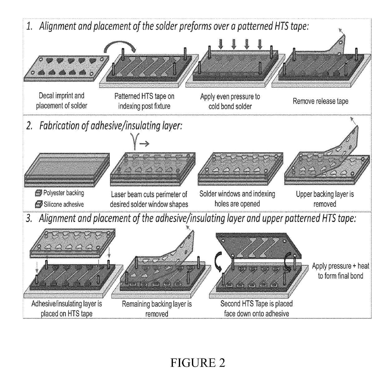
[0040]The double-sided adhesive (DSA) is 1 mil thick (adhesive only) and initially protected by a liner on both sides.

[0041]The DSA is rated for operation over a wide temperature range (−185 to 260° C.). Openings that coincide with the ends of the HTS filaments are laser-machined through the adhesive.

[0042]This adhesive (with one liner removed) is carefully aligned and placed over one of the HTS tapes using the alignment jig.


PUM

PropertyMeasurementUnit
Temperatureaaaaaaaaaa

Abstract

This disclosure teaches methods for making high-temperature superconducting striated tape combinations and the product high-temperature superconducting striated tape combinations. This disclosure describes an efficient and scalable method for aligning and bonding two superimposed high-temperature superconducting (HTS) filamentary tapes to form a single integrated tape structure. This invention aligns a bottom and top HTS tape with a thin intervening insulator layer with microscopic precision, and electrically connects the two sets of tape filaments with each other. The insulating layer also reinforces adhesion of the top and bottom tapes, mitigating mechanical stress at the electrical connections. The ability of this method to precisely align separate tapes to form a single tape structure makes it compatible with a reel-to-reel production process.

Description

REFERENCE TO RELATED APPLICATION[0001]This application is a non-provisional of, and claims priority to and the benefits of, U.S. Provisional Patent Application No. 62 / 598,541 filed on Dec. 14, 2017, U.S. Provisional Patent Application No. 62 / 598,539 filed on Dec. 14, 2017, and U.S. Provisional Patent Application No. 62 / 728,650 filed on Sep. 7, 2018, the entireties of each are hereby incorporated by reference.BACKGROUND[0002]This disclosure concerns high-temperature superconducting striated tape and methods of making high-temperature superconducting striated tape combinations.[0003]The term ‘tape’ in this invention is generalized to mean structures that do or do not contain adhesive.[0004]The zero DC resistance property of HTS enable them to carry large currents even in significant magnetic fields and thus enables the reduction of conductor weight and volume of various systems.[0005]The second generation (2G) HTS coated conductors used in such DC applications consist of flat metal ta...

Claims


Application Information

Patent Timeline
IPC IPC(8): H01L39/14H01L39/24
CPCH01L39/143H01L39/248B23K35/0222B23K35/264Y02P80/30H05K3/3478H05K2203/107H05K2203/167H05K2203/1545H05K2203/0531H10N60/203H10N60/0801Y02E40/60H01B12/06H01B13/0036H10N60/0688H10N60/01B23K2101/42B23K1/0016B23K3/0623H01L21/67092H01L21/681H01L21/6836H01L21/6838H01L24/03H01L2221/68309H01L2224/03003H01L2224/0311H01L2224/05109H01L2224/05113H01L2924/01322H01L2924/014
Inventor PRESTIGIACOMO, JOSEPH C.AUYEUNG, RAYMOND C.Y.OSOFSKY, MICHAEL S.
Owner UNITED STATES OF AMERICA
Learn More