Anchor platform assembly

a platform and platform technology, applied in the direction of snow traps, heat collector mounting/support, lighting and heating apparatus, etc., can solve the problems of equipment attachment points infiltration, eventual roof leakage, cracks in adhesive or glue,

Active Publication Date: 2019-06-27
LN1 INC
View PDF21 Cites 17 Cited by
  • Summary
  • Abstract
  • Description
  • Claims
  • Application Information

AI Technical Summary

Benefits of technology

[0008]It is yet a further object of the present invention to provide such a novel anchor platform which is universally adaptable for anchoring and mounting a multitude and wide variety of roof accessory structures including, interalia, solar panels, satellite dishes, safety rails, glass railings, HVAC heating and air conditioning equipment, decorative sculptures, holiday ornaments, and the like, etc., while at the same time providing a watertight connection.

Problems solved by technology

In the roofing industry, there are many problems with water infiltration at equipment attachment points, particularly when flashing is not incorporated and / or sealants are solely relied on.
In fact, over time, these heavy structures as a result of normal repetitive roof movement or shifting caused by, e.g., settling, temperature changes, and / or high winds, cause cracks in the adhesive or glues employed and cause eventual roof leaks.
As a result, it is difficult for many of the installers to provide guarantees or obtain insurance against water or moisture damage caused by such conventional anchoring systems.

Method used


Image

  • Anchor platform assembly
  • Anchor platform assembly
  • Anchor platform assembly

Examples


first embodiment

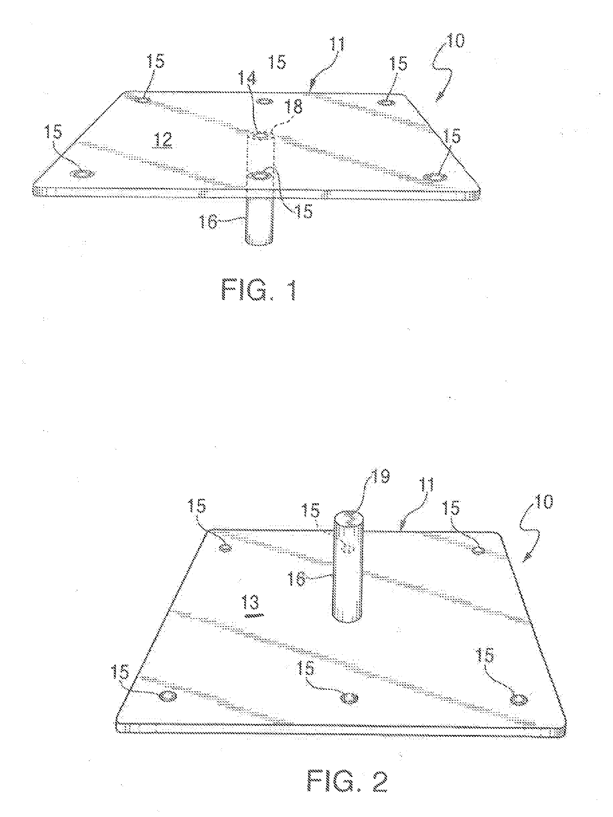
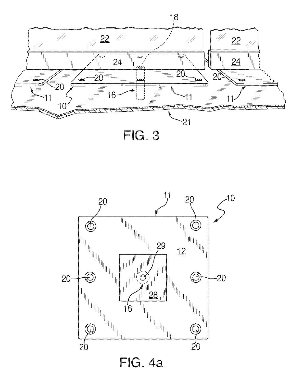
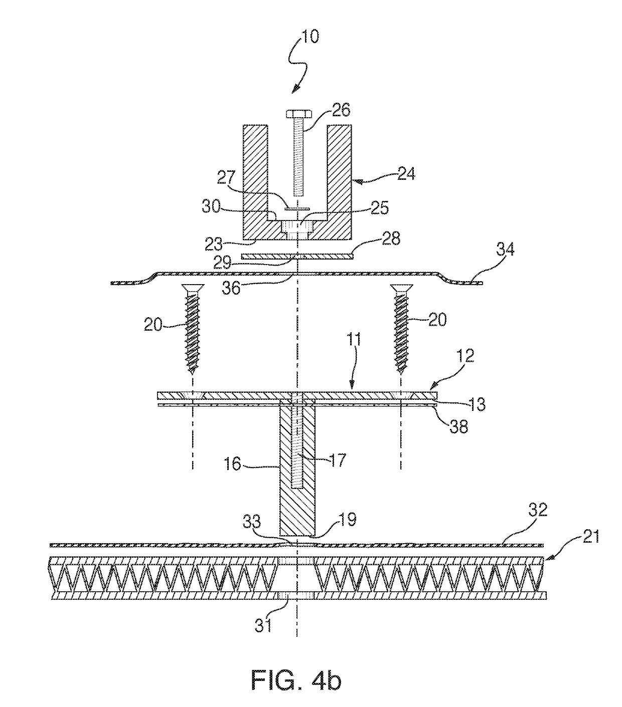
[0033]Turning now in detail to the drawings and, in particular, to FIGS. 1-4c thereof, therein illustrated is a novel anchor platform assembly embodying the present invention, generally designed by reference numeral 10, for anchoring roof accessory structures to roofs and other raised, flat and / or pitched structures, such as terraces, balconies, stairs and the like. The main component of the anchor platform assembly is the anchor baseplate, generally designated by reference numeral 11, which preferably is made of stainless steel (but could be made of other metals, such as aluminum, bronze, etc.), and is square or rectangular shaped and has a top surface 12 and a bottom surface 13. The anchor baseplate 11 has an internally-threaded central through bore 14 and six spaced apart peripheral through bores 15 positioned radially outward from the center bore 14 and generally adjacent to the periphery of the baseplate 11. In this embodiment, the anchor baseplate 11 also includes a preferably...

third embodiment

[0042]FIGS. 6a and 6b illustrate the anchor baseplate assembly 10″ and, in a similar fashion, respectively show an exploded cross-sectional view and a fully mounted cross-sectional view of this third anchor platform assembly embodiment.

[0043]The elements shown in this third embodiment are the same as shown in FIGS. 5a and 5b with the exception that the lower portion 38 of cylindrical post 16″ is externally threaded but is otherwise identical to the cylindrical post 16′. In this embodiment, a nut 39 and washer 41 are threaded onto the externally threaded surface 38 of the cylindrical post 16″ so that in the fully assembled state shown in FIG. 6b, the nut 39 and washer 41 are tightened against the lower surface of the metal roof deck 21′ to provide a stronger point of attachment while at the same time preventing roof leaks at the point of attachment via the blind bore 17′ and the closed end 19 of the cylindrical post 16″.

[0044]FIGS. 7a and 7b illustrate a novel accessory support stand...

fourth embodiment

[0045]Finally, FIGS. 8a-8e disclose the anchor platform assembly 10′ wherein the anchor baseplate 11″ has a lower square-shaped, planar base portion 50 and a frusto-pyramidal upper portion which defines four upwardly tapered sidewalls 51 and a square-shaped planar top wall 52. The top wall 52 has a internally threaded, centrally-disposed blind bore 54 and each of the sidewalls 51 have a recessed, generally cylindrical cutout or cavity 55 which opens onto a throughbore 56 which extends through the bottom portion 50 and in turn, opens on the bottom surface 57 thereof.

[0046]As seen in FIGS. 8d and 8e which respectively show an exploded cross-sectional view and a fully mounted cross-sectional view of this fourth embodiment of the anchor platform assembly, the top wall 52 is used to anchor an object 24 to the roof structure via its internally threaded central blind bore 54. Lag screws 53 are inserted in each of the sidewall throughbores 55 to affix the anchor baseplate 11′″ to the metal ...


PUM


Abstract

An anchor platform assembly for anchoring an object to a raised, generally flat roof-like structure, has an anchor baseplate having a top surface and a bottom surface, and an internally threaded blindbore extending at least partially from the top surface generally towards the bottom surface and fasteners for fastening an object to the anchor baseplate via its blindbore, and for fastening the anchor baseplate to a top surface of a roof-like structure. The assembly is especially intended for supporting, e.g., glass railings on balconies, terraces and flat roofs and for mounted solar panels on both flat and pitched roofs which provides strength and affords watertight performance.

Description

BACKGROUND OF THE INVENTION1. Field of the Invention[0001]An anchor platform assembly for anchoring roof accessory structures to roofs and other raised, flat and pitched structures, terraces, balconies and the like, e.g., railings and solar panels, while providing both strength and watertight performance.2. Brief Description of the Prior Art[0002]Various methods for mounting and waterproofing roof equipment, accessory structures or the like, which are attached to sloped or flat roofs, building terraces, roof decks, etc. are well known. In the roofing industry, there are many problems with water infiltration at equipment attachment points, particularly when flashing is not incorporated and / or sealants are solely relied on. A variety of sheathing methods and combinations thereof are used as a water and moisture barrier on such structures such as asphalt roof tiles, poured or sheeted plastic or rubber membranes and the like. Currently, more and more roof heavy roof structures are being...

Claims


Application Information

Patent Timeline
Patent Type & Authority Applications(United States)
IPC IPC(8): E04D13/00F16B9/02
CPCE04D13/00F16B9/026E04F11/1812E04F11/1853F16B17/006F16B33/004F16B11/006F16B5/0614F16B9/054F16B9/056Y02E10/47E04F13/00H02S20/23F24S25/40E04H12/22E02D27/42E04D13/14E04D1/34E02D5/74F16B9/02
Inventor NILL, LANCE
Owner LN1 INC
Why Eureka
Try Eureka