Methods for pre-charging carbon dioxide snow

a technology of carbon dioxide snow and precharging method, which is applied in the direction of domestic cooling apparatus, lighting and heating apparatus, instruments, etc., can solve the problems of dry ice to lose its cooling effect, the clinical site cannot maintain a sufficient supply of dry ice, and the laborious assembly of the insulated box and the loading of dry ice,

Active Publication Date: 2019-06-27
PRAXAIR TECH INC
View PDF4 Cites 2 Cited by
  • Summary
  • Abstract
  • Description
  • Claims
  • Application Information

AI Technical Summary

Problems solved by technology

Assembly of the insulated box and loading of the dry ice can be labor intensive.
There may also be considerable cost and inconvenience associated with maintaining a sufficient supply of dry ice at the clinical site.
Additionally, the failure to use such dry ice within certain duration can result in significant sublimation losses that cause the dry ice to lose its cooling effect.
Further, the insulated box is typically not reusable and must be discarded, thereby creating waste.
Other drawbacks also exist with the transport of samples in conventional insulated boxes.
The interior sample space may be uniformly near dry ice temperature upon initial full dry ice loading, but as the dry ice sublimates, significant temperature gradients can arise within the interior sample space, potentially compromising sample quality.
However, should delays or disruptions occur in the shipping lanes, the samples can degrade.
As a result of such delays during shipment, additional dry ice may be required to be loaded into the box during transit, which results in increased cost and logistical complexity to the shipment.
However, such liquid nitrogen-based vapor vessels suffer from drawbacks.
One drawback is the time and labor involved in the preparation of the vessel.
Substantial handling of the cryogenic liquid nitrogen is necessary, and significant time is required to prepare the liquid nitrogen shipper prior to its usage.
Further, the costs associated with the use of liquid nitrogen-based vapor vessels are significantly higher than alternative dry ice vessels.

Method used


Image

  • Methods for pre-charging carbon dioxide snow
  • Methods for pre-charging carbon dioxide snow
  • Methods for pre-charging carbon dioxide snow

Examples


Embodiment Construction

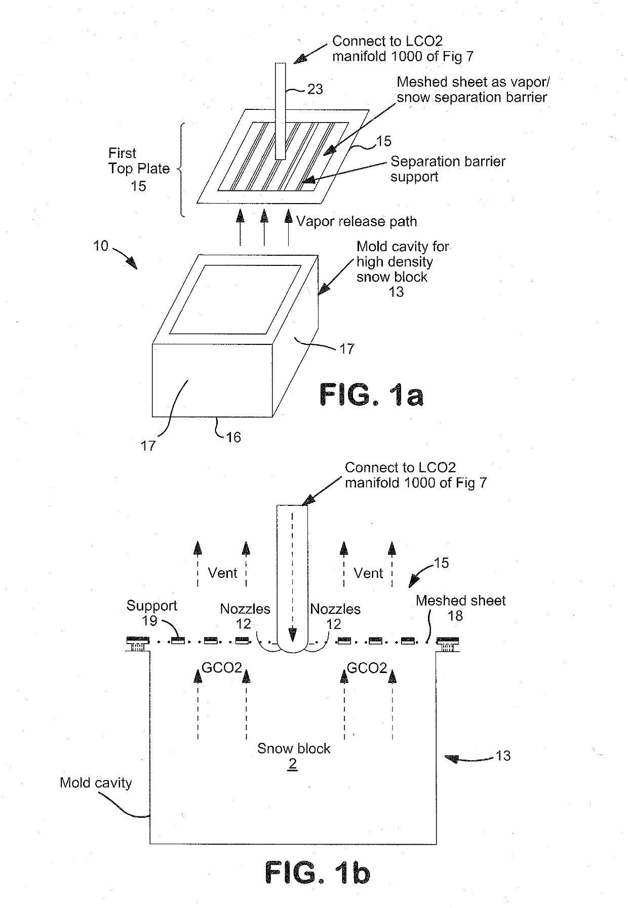
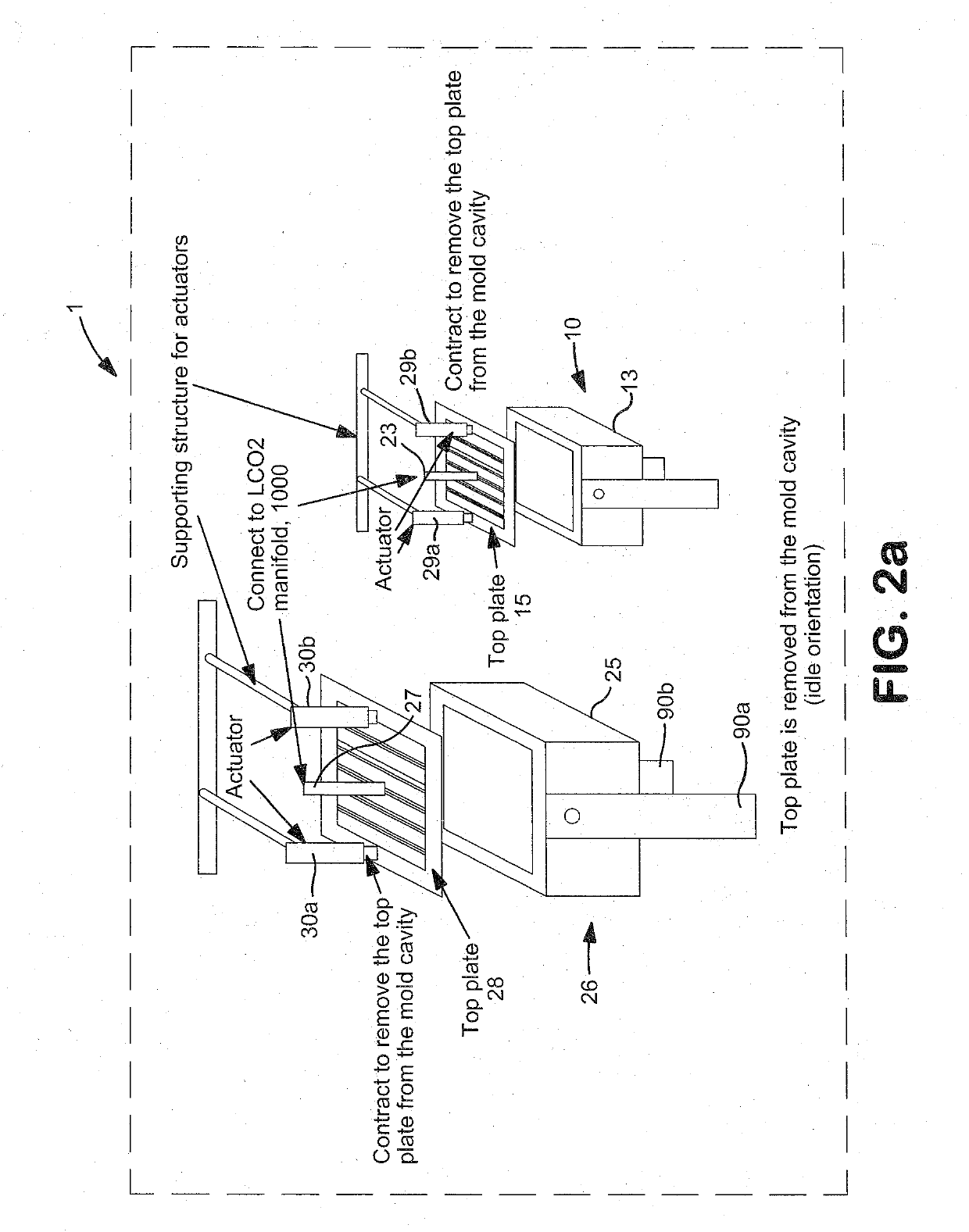
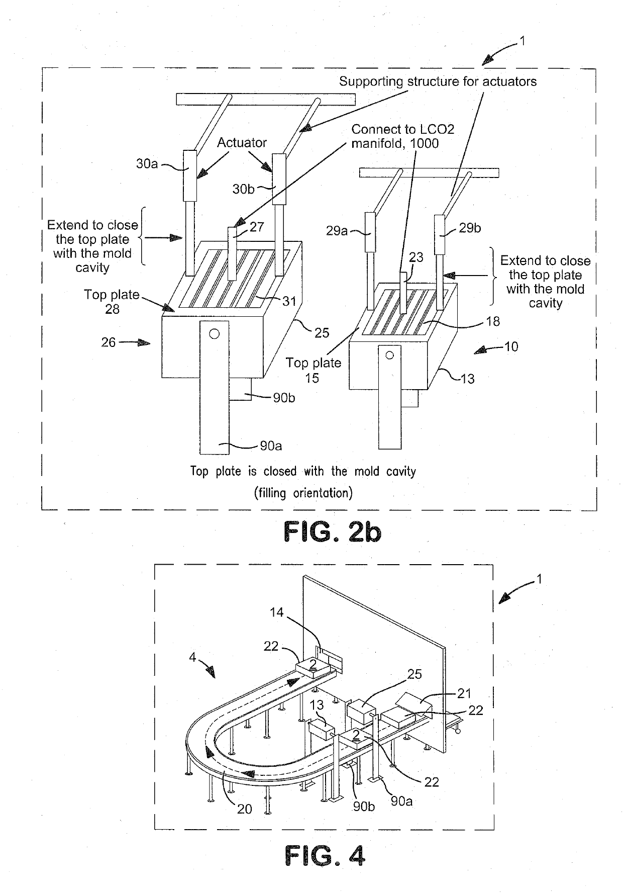
[0027]As will be described, in one aspect, the present invention offers a method for automatically generating various size CO2 snow blocks available from an automatic dispensing station. A user can readily access the generated CO2 snow block from an inlet and outlet accessing window of a conveyor system located within the dispensing station. The on-demand generation of the present invention eliminates the need for a user to maintain an inventory of CO2 snow block or dry ice on-site.

[0028]It should be understood that the term “CO2 snow” and “dry ice” have the same meaning and may be used interchangeably herein and throughout to mean particles of solidified CO2.

[0029]“CO2 snow block” or “CO2 block,” both of which may be used interchangeably herein and throughout, are intended to mean the creation of CO2 snow particles in a substantially block-like form of any shape consisting of tightly held-particles.

[0030]“CO2 fluid” as used herein means any phase including, a liquid phase, gaseous ...


PUM

PropertyMeasurementUnit
temperatureaaaaaaaaaa
angleaaaaaaaaaa
densityaaaaaaaaaa

Abstract

Manual and automated methods of pre-charging an empty or partially empty insulated container with CO2 snow are provided. A first location such as a charging location charges CO2 liquid into a container to create a pre-charged container with CO2 snow. The charging location prepares the pre-charged container for delivery to a second location, either by itself, or through a third party. The second location may be a clinical site, which upon receipt of the pre-charged container, loads a perishable item such as a biological sample into the pre-charged container. A user receives the pre-charged container with perishable item and removes the perishable item from the pre-charger container for testing (e.g., biological testing). Depending on the level of depletion of the CO2 snow in the pre-charged container, the user returns the depleted container to the first location or the intermediate location.

Description

CROSS REFERENCE TO RELATED APPLICATION[0001]This application claims the benefit of priority to U.S. provisional application Ser. No. 62 / 608,278 filed Dec. 20, 2017, the disclosure of which is incorporated by reference herein in its entirety.FIELD OF INVENTION[0002]This invention relates to manual and automated methods for pre-charging CO2 snow within a container.BACKGROUND OF THE INVENTION[0003]Drug development continues to be a major endeavor in the pharmaceutical industry. Drug development requires clinical trials to establish the safety and efficacy of new treatments. Today, in the United States, alone, there are a large number of on-going clinical trials in various stages. Each clinical trial can involve hundreds to thousands of patients who have volunteered to the administering of certain experimental drugs. Generally speaking, as part of the clinical trial, biological samples (e.g., tissue, urine, blood samples) are collected from participants at a clinical site, such as a hos...

Claims


Application Information

Patent Timeline
Patent Type & Authority Applications(United States)
IPC IPC(8): F25D3/12C01B32/55G06Q10/08F25D25/00A01N1/02
CPCF25D3/125C01B32/55G06Q10/0832F25D25/005A01N1/0273G06Q10/0837F25D2500/06F25D2331/8014F25D2303/085F25D2331/809A01N1/0252F17C6/00
Inventor SEVER, ROBERTBURSAC, RANKOZHOU, YING
Owner PRAXAIR TECH INC
Why Eureka
Try Eureka