Method and apparatus for detecting cylinder and cylindrical converging lens

a cylindrical shape and detection technology, applied in the field of optical instrument detection, can solve the problems of cylinder application restrictions, cylinder detection technology development relatively slowly, and generally cannot meet current application requirements, so as to reduce the processing and detection difficulty of the detection tool and reduce the number of system errors in measuremen

Active Publication Date: 2019-07-11
SUZHOU UNIV
View PDF0 Cites 3 Cited by
  • Summary
  • Abstract
  • Description
  • Claims
  • Application Information

AI Technical Summary

Benefits of technology

[0027]Compared with the prior art, the present invention has the following obvious advantages: (1) a high-precision detection tool such as a standard cylindrical lens or a computer-generated hologram configured to generate a cylindrical wave does not need to be processed in advance, so that processing and detection difficulty of the detection tool is reduced; (2) two cylindrical converging lenses and a cylindrical lens are combined and mutually detected, so that system errors in measurement are reduced. The apparatus can implement high-precision detection of a convex or concave cylindrical lens and a cylindrical converging lens.

Problems solved by technology

However, applications of cylinder are always restricted by optical fabrication and detection technologies.
Currently, the optical fabrication technology develops rapidly, but the detection technology to cylinder develops relatively slowly and generally cannot satisfy current application requirements.
Therefore, a high-precision detection technology to cylinder becomes a key factor that restricts applications of cylinder.
However, high-precision detection to the shape of cylinders cannot be implemented by using common detection technologies because of special optical characteristics of the cylinders.
The auxiliary plane method cannot detect an asymmetric deviation of a cylindrical shape.
Usually, a minimum spacing between scribe lines of holographic gratings is very small, which is difficult to process and it is difficult to ensure precision.
In the standard cylinder method, a standard cylinder with very high precision needs to be processed first, and the detection of the standard cylinder is still significantly difficult.
Moreover, the shape precision of the standard cylinder directly affects the measurement precision of a cylinder to be detected, which increases the costs of processing and detection.
Consequently, processing is difficult and the cost is high.

Method used


Image

  • Method and apparatus for detecting cylinder and cylindrical converging lens
  • Method and apparatus for detecting cylinder and cylindrical converging lens
  • Method and apparatus for detecting cylinder and cylindrical converging lens

Examples


embodiment 1

[0057 provides a method for detecting a cylinder and a cylindrical converging lens, including the following steps:

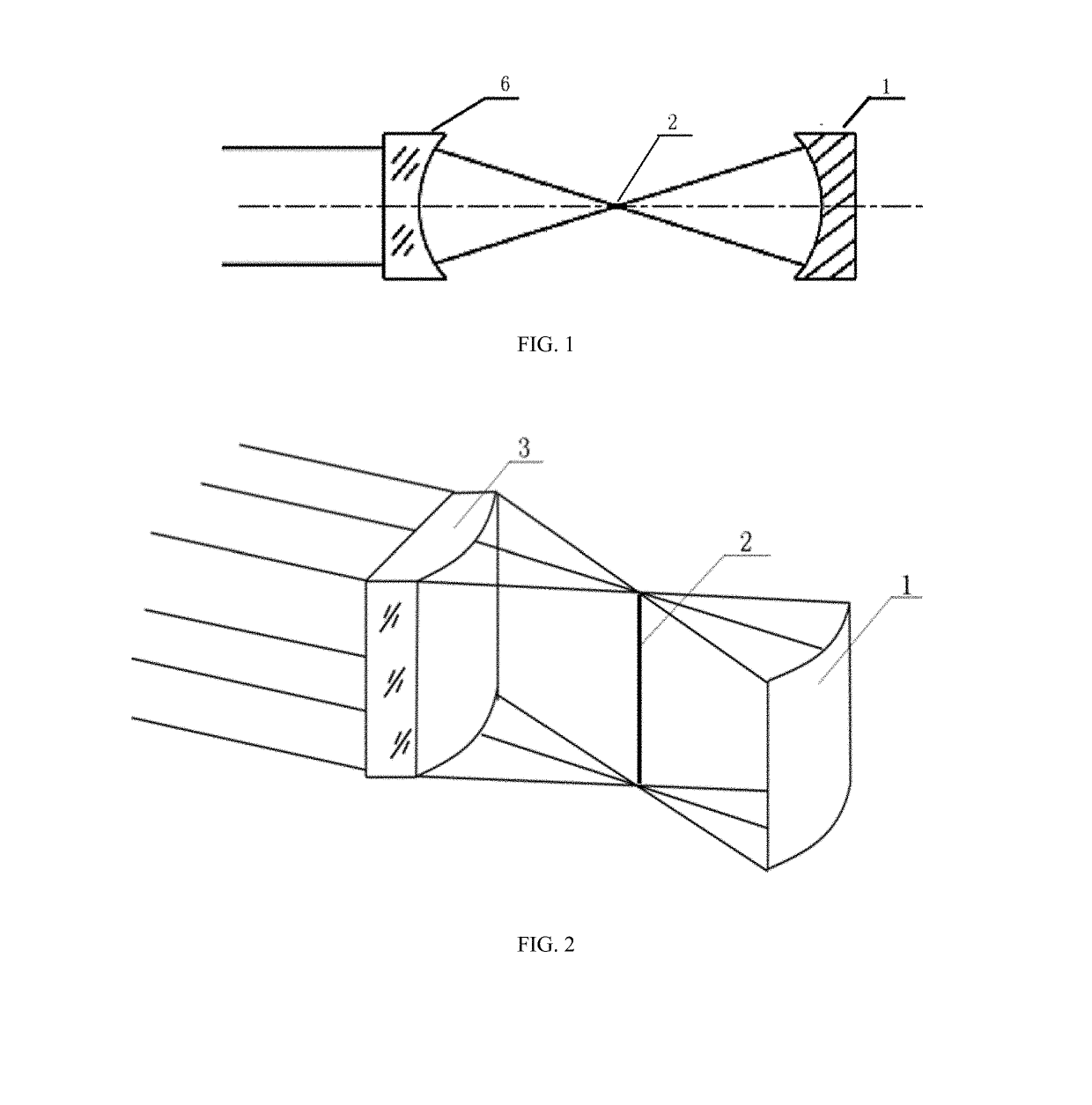
[0058]Step 1) is a step of collecting wavefront error data of a combination of a first cylindrical converging lens 3 and a to-be-tested cylinder 1. As shown in FIG. 2 and FIG. 8, a commercial digital wavefront interferometer, the first cylindrical converging lens 3, and the to-be-tested cylinder 1 are sequentially arranged in a direction of an optical axis. A 4-inch plane standard lens is selected as a standard lens of the interferometer and is configured to provide parallel light. A focal length of the first cylindrical converging lens 3 is 100 mm. The first cylindrical converging lens 3 enables wavefronts of parallel light to converge into a cylindrical wave and intersect at a focal line 2. The to-be-tested cylinder 1 is a concave cylinder having a curvature radius of 45 mm. The position of the to-be-tested cylinder is adjusted to enable a center line of curvature of t...

embodiment 5

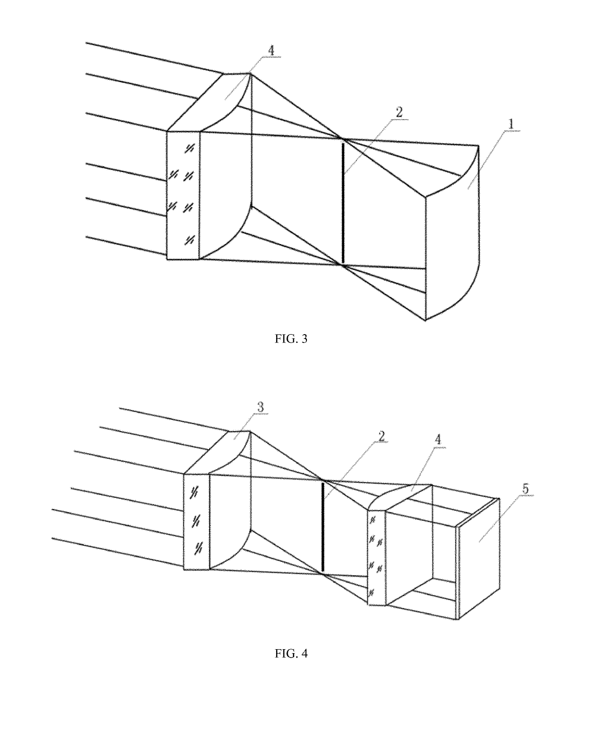
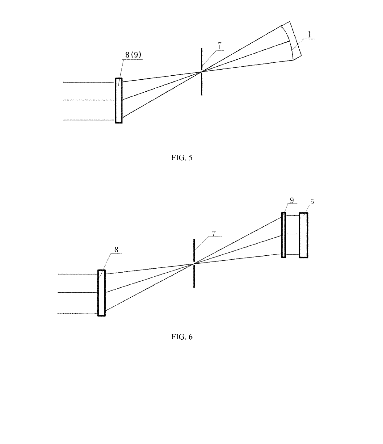
[0065 provides an apparatus for detecting a cylinder and a cylindrical converging lens. As shown in FIG. 7, the apparatus includes a horizontal substrate 14, a first adjusting frame 10, a second adjusting frame 11, and a third adjusting frame 12 that are disposed on the horizontal substrate 14, a horizontal rotating platform 13 fixed on the second adjusting frame 11, a first cylindrical converging lens 3 disposed on the first adjusting frame 10, a second cylindrical converging lens 4 disposed on the rotating platform 13, and a to-be-tested cylinder 1 and a standard planar reflector 5 that are clamped on the second adjusting frame 11.

[0066]The first cylindrical converging lens 3 is optically coaxial with the second cylindrical converging lens 4 and the standard planar reflector 5 to form a first combined test area 15. The first cylindrical converging lens 3 is optically coaxial with the to-be-tested cylinder 1 to form a second combined test area 16. The second cylindrical converging ...


PUM


Abstract

A method and an apparatus for detecting a cylinder and a cylindrical converging lens are disclosed. In particular, a method for non-contact interference detection of a cylindrical shape is disclosed. Two converging lenses which modulate parallel light into cylindrical waves are combined with a to-be-tested cylinder respectively. Wavefront error data of the combination of the converging lens and the to-be-tested cylinder and wavefront error data of the combination of the two cylindrical converging lenses are obtained. Shape error data of the to-be-tested cylinder, the two cylindrical converging lenses is obtained respectively by using a difference algorithm and a wavefront recovery algorithm. In the technical solution, a detection light path is simple, and shape detection of a cylinder with relatively high precision can be implemented without using a high-precision detection tool calibrated in advance. The technical solution is particularly suitable for cylinder processing in the field of optical processing.

Description

FIELD OF THE INVENTION[0001]The present invention relates to the technical field of optical instrument detection, and in particular, to a method and an apparatus for non-contact interference detection of a cylindrical shape.BACKGROUND OF THE INVENTION[0002]A meridional section and a sagittal section of a cylindrical optical element have different focal powers. Therefore, cylindrical optical elements are widely applied to optical systems that produce distorted images. In the civilian field, cylindrical optical elements are usually applied to anamorphic lenses, linear detector lighting, holographic lighting, barcode scanning, optical information processing, among other aspects. In recent years, with rapid development of intense laser systems, synchrotron radiation beamlines, linear test instruments, and the like, people require increasingly high cylindrical precision. However, applications of cylinder are always restricted by optical fabrication and detection technologies. Currently, ...

Claims


Application Information

Patent Timeline
Patent Type & Authority Applications(United States)
IPC IPC(8): G01B11/24G01B9/02
CPCG01B11/2441G01B9/02038G01M11/005
Inventor GUO, PEIJICHEN, XIFAN, JIANBIN
Owner SUZHOU UNIV
Why Eureka
Try Eureka