Wireless power control method and device for wireless charging

a wireless power transmission device and control method technology, applied in the direction of dc-ac conversion without reversal, inductance, transportation and packaging, etc., can solve the problems of reducing the convenience of use, reducing the efficiency of wireless power transmission, and increasing the difficulty of charging the battery. the effect of preventing heat generation

Active Publication Date: 2019-07-11
LG INNOTEK CO LTD
View PDF0 Cites 37 Cited by
  • Summary
  • Abstract
  • Description
  • Claims
  • Application Information

AI Technical Summary

Benefits of technology

[0018]Embodiments provide a wireless power control method and device for adaptively determining an inverter type and a power control mode according to the intensity of transmission power.
[0074]The method, device and system according to the embodiments have the following effects.
[0075]Embodiments provide a wireless power control method and device capable of preventing heat generation from occurring in a wireless power transmission device.
[0077]According to embodiments, heat generation in a wireless power transmission device may be minimized without adding a separate hardware heat dissipation structure.
[0078]In addition, user convenience may be enhanced as a wider charging area is provided using a plurality of transmission coils.
[0079]In addition, as only one of a plurality of identical circuits needs to be used, the size of the wireless power transmitter may be reduced, and decrease in the number of parts used may lead to cost reduction.

Problems solved by technology

Accordingly, power supply to these devices or sensors is becoming a new challenge.
In addition, as the types of mobile devices such as Bluetooth handsets and iPods, as well as mobile phones, rapidly increase in number, charging the battery has required time and effort.
However, this scheme may be used only at a limited distance and in a limited space, and has somewhat low energy transfer efficiency.
As various devices are equipped with a wireless charging function and the intensity of power required by a wireless power reception device increases, heat generated in a drive circuit and a transmission coil may damage the devices.
However, not only does the heat dissipation effect of such structures fail to meet expectations, but it is also limited by cost and mechanism limitations.

Method used


Image

  • Wireless power control method and device for wireless charging
  • Wireless power control method and device for wireless charging
  • Wireless power control method and device for wireless charging

Examples


Embodiment Construction

[0108]Hereinafter, an apparatus and various methods to which embodiments of the present disclosure are applied will be described in detail with reference to the drawings. As used herein, the suffixes “module” and “unit” are added or used interchangeably to facilitate preparation of this specification and are not intended to suggest distinct meanings or functions.

[0109]In the description of the embodiments, it is to be understood that, when an element is described as being “on” / “over” or “beneath” / “under” another element, the two elements may directly contact each other or may be arranged with one or more intervening elements present therebetween. Also, the terms “on” / “over” or “beneath” / “under” may refer to not only an upward direction but also a downward direction with respect to one element.

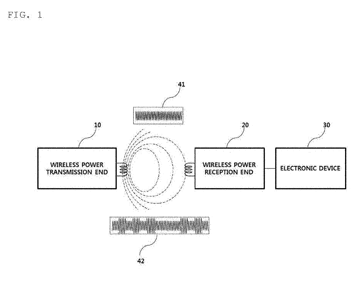
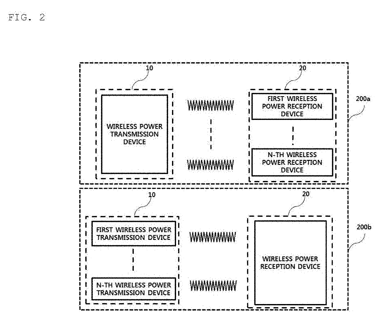
[0110]For simplicity, in the description of the embodiments, “wireless power transmitter,”“wireless power transmission device,”“transmission end,”“transmitter,”“transmission device,”“transmissi...


PUM

PropertyMeasurementUnit
transmission distanceaaaaaaaaaa
operating frequencyaaaaaaaaaa

Abstract

The present invention relates to a wireless power control method and device for wireless charging, and the wireless power control method of a wireless power transmitter according to an embodiment of the present invention may comprise: a step of receiving, from a wireless power receiver, a first feedback signal requesting power control; a step of determining the intensity of a first transmission power on the basis of the first feedback signal; a step of determining an inverter type and a power control method which correspond to the determined intensity of the first transmission power; a step of activating an inverter corresponding to the determined inverter type; and a step of controlling the intensity of alternating current power outputted from the inverter, by using the determined power control method.

Description

TECHNICAL FIELD[0001]Embodiments relate to a wireless power transmission technique, and more particularly, to a wireless power control method and device for wireless charging.BACKGROUND ART[0002]Recently, with rapid development of information and communication technology, a ubiquitous society based on information and communication technology is being established.[0003]In order for information communication devices to be connected anywhere and anytime, sensors with a built-in computer chip having a communication function should be installed in all facilities throughout society. Accordingly, power supply to these devices or sensors is becoming a new challenge. In addition, as the types of mobile devices such as Bluetooth handsets and iPods, as well as mobile phones, rapidly increase in number, charging the battery has required time and effort. As a way to address this issue, wireless power transmission technology has recently drawn attention.[0004]Wireless power transmission (or wirel...

Claims


Application Information

Patent Timeline
Patent Type & Authority Applications(United States)
IPC IPC(8): H02J50/12H02J50/40H02J7/02H01F27/28H02M7/48
CPCH02J50/12H02J50/40H02J7/025H01F27/288H02M7/48H02J50/90H02M1/32H01F38/14H02J7/00712Y02B70/10H02M1/0058H02M7/4818H02M3/003H02J50/402H02M3/33573H02M3/33571H02M3/01H02J7/02H02J50/80H02J50/70
Inventor PARK, JAE HEE
Owner LG INNOTEK CO LTD
Why Eureka
Try Eureka