Door control device

a control device and door technology, applied in the field of door control devices, to achieve the effect of favorable pullability

Active Publication Date: 2019-07-18
FUJI ELECTRIC CO LTD
View PDF0 Cites 3 Cited by
  • Summary
  • Abstract
  • Description
  • Claims
  • Application Information

AI Technical Summary

Benefits of technology

[0008]It is possible to provide a door control device with favorable pullability.

Problems solved by technology

However, Patent Document 1 does not disclose that, in a state in which sliding doors are closed while sandwiching an object between the sliding doors or between a frame and the slid door, a user can easily pull out the object.

Method used


Image

  • Door control device
  • Door control device
  • Door control device

Examples


embodiment

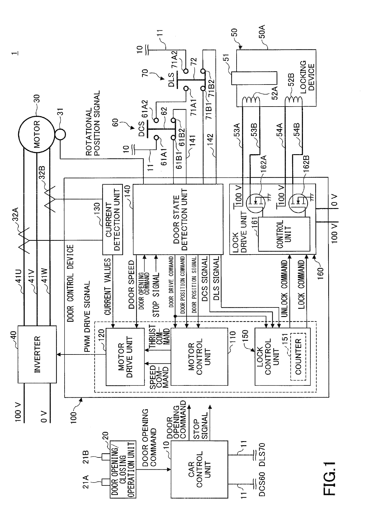
[0017]FIG. 1 is a diagram illustrating a circuit configuration of a door device of a car 1. Here, the car 1 is a train car that is operated by a railroad company or the like, and includes a door driven by a motor 30. The train is not limited to an electric train as long as the train includes one or more doors that are driven by the motor 30. In FIG. 1, a configuration relating to an opening / closing operation and an opening / closing control of a door is illustrated, and the illustration of the door is omitted.

[0018]The car 1 includes a car control unit 10, a door opening / closing operation unit 20, a motor 30, an encoder 31, current sensors 32A and 32B, an inverter 40, a locking device 50, a Door Close Switch (DCS) 60, a Door Lock Switch (DLS) 70, and a door control device 100.

[0019]The car control unit 10 is an information processing device that controls an operation of the car 1. In a case in which a plurality of cars 1 are connected in a train, one car control unit 10 is provided fo...


PUM


Abstract

A door control device includes: an electric motor control unit configured to drive, in response to a closing command for closing a door that is driven to be opened and closed by an electric motor, the electric motor; a door closed state detection unit configured to detect a closed state of the door; and a lock command output unit configured to output a lock command to lock a locking device of the door, upon the closed state being detected when a predetermined waiting time has passed after the electric motor was driven by the electric motor control unit in response to the closing command and the closed state was detected by the door closed state detection unit.

Description

CROSS-REFERENCE TO RELATED APPLICATION[0001]This application is a continuation application of International Application PCT / JP2017 / 037427 filed on Oct. 16, 2017 and designated the U.S., the entire contents of which are incorporated herein by reference.BACKGROUND OF THE INVENTION1. Field of the Invention[0002]The present invention relates to a door control device.2. Description of the Related Art[0003]Conventionally, Patent Document 1 describes a door closing device of a sliding door in which, to the sliding door that opens and closes linearly in a frame of a car, a closing receiver and an opening receiver located in its opening direction are attached. In the door closing device, a drive protrusion of a motor that opens and closes the sliding door is located between the closing receiver and the opening receiver. In the door closed state of the sliding door, the drive protrusion and the closing receiver are in contact and a gap X between the drive protrusion and the opening receiver i...

Claims


Application Information

Patent Timeline
Patent Type & Authority Applications(United States)
IPC IPC(8): E05F15/79
CPCE05F15/79E05F15/635E05Y2900/51B61D19/005B61D19/02E05F15/655E05F15/659E05Y2900/531E05Y2201/22E05Y2400/36E05Y2400/354E05B85/00
Inventor FUJITA, KENJIKITABATA, ATSUSHI
Owner FUJI ELECTRIC CO LTD
Why Eureka
Try Eureka