Sidewall with buckstay for a metallurgical furnace

Active Publication Date: 2019-07-18
SYST SPRAY COOLED
View PDF3 Cites 5 Cited by
  • Summary
  • Abstract
  • Description
  • Claims
  • Application Information

AI Technical Summary

Problems solved by technology

However, as the hot plate expands and contracts relative to the attached buckstay due to heat loads, cracking of the hotplate may result because of stress caused by restraint of the hot plate expansion and contraction, which may pot

Method used


Image

  • Sidewall with buckstay for a metallurgical furnace
  • Sidewall with buckstay for a metallurgical furnace
  • Sidewall with buckstay for a metallurgical furnace

Examples


Embodiment Construction

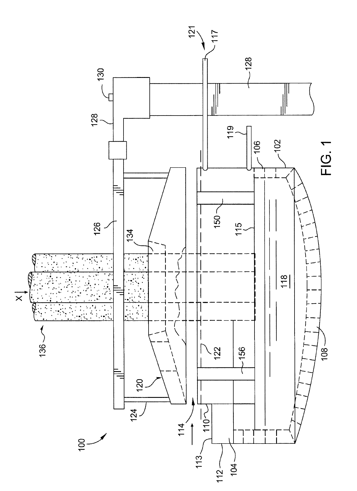
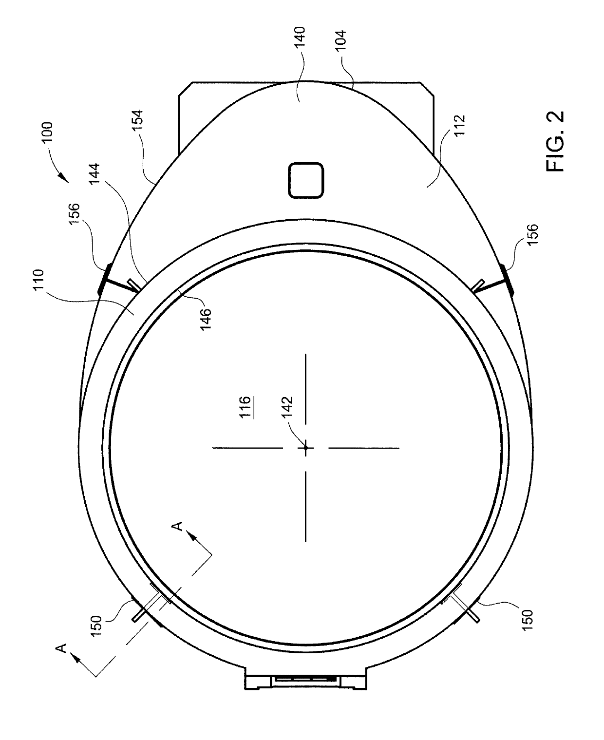
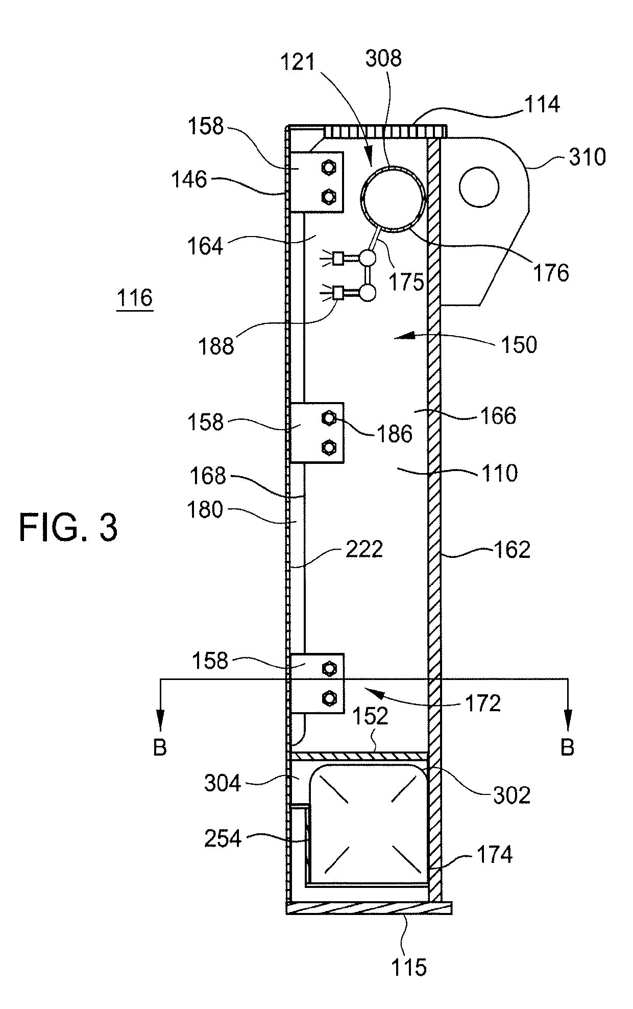
[0018]The present invention is directed to a metallurgical electric arc furnace having a sidewall. In one embodiment, the sidewall has an outer wall and a hot plate having a bracket affixed thereto, and a buckstay mechanically coupled to the outer wall and the hot plate. The buckstay includes a buckstay flange and a buckstay web extending from the buckstay flange. The buckstay web includes a first end coupled to the buckstay flange and a second end second end mechanically coupled to the hot plate. The second end is movably fastened to the bracket. Since the buckstay is moveably fastened to the hot plate, the outer wall is also moveable relative to the hot plate, thus allowing the mechanical integrity of the sidewall to be maintained even after many thermal cycles. Moreover, as the buckstay is spaced separate to the hot plate, coolant present on the hot plate is not blocked by the buckstay from flowing freely across the hot plate. Thus, spray cooling of the hot plate is more effectiv...


PUM


Abstract

A sidewall for a metallurgical furnace and a metallurgical furnace having the same are described herein. In one example, a sidewall of a metallurgical furnace is provided that includes an outer wall, a hot plate and a buckstay. The hot plate is coupled in a spaced apart relation to the outer wall. The buckstay is mechanically coupled to the outer wall and the hot plate. The buckstay includes a buckstay web extending from a buckstay flange. The buckstay web includes a first end coupled to the buckstay flange, and a second end mechanically and movably coupled to the hot plate.

Description

BACKGROUND OF THE DISCLOSUREField of the Disclosure[0001]Embodiments of the present disclosure relates generally to a sidewall with one or more buckstays for a sidewall of a metallurgical furnace.Description of the Related Art[0002]Metallurgical furnaces (e.g., an electric arc furnace) are used in the processing of molten metal materials. The electric arc furnace heats charged metal in the furnace by means of an electric arc from a graphite electrode. The electric current from the electrode passes through the charged metal material forming a molten bath of the metal materials. The molten bath generally includes the molten material, such as steel, and slag (a byproduct of steelmaking).[0003]A metallurgical furnace has a number of components, including a roof that is retractable, a hearth that is lined with refractory brick, and a sidewall that sits on top of the hearth. The metallurgical furnace typically rests on a tilting platform to enable the furnace to tilt about an axis. During...

Claims


Application Information

Patent Timeline
IPC IPC(8): F27D1/12F27D1/00F27D1/14F27D11/08
CPCF27D1/12F27D1/0033F27D1/14F27D11/08F27D1/145F27D2001/0079F27D2009/0016F27B3/10C21C5/5211Y02P10/20F27B1/12F27D9/00
Inventor FERGUSON, SCOTT A.TEMKINA, MARINA K.WARD, TROY D.
Owner SYST SPRAY COOLED
Why Eureka
Try Eureka