
Semiconductor device and method of manufacturing the same

Active Publication Date: 2019-07-25
DENSO CORP
View PDF6 Cites 0 Cited by
  • Summary
  • Abstract
  • Description
  • Claims
  • Application Information

AI Technical Summary

Benefits of technology

This patent describes a semiconductor device that prevents damage caused by excess solder during the manufacturing process. The device includes grooves on the side surface of the first conductor to guide excess solder away from the semiconductor element. This reduces stress on the semiconductor and improves reliability of the semiconductor device. The position of the groove can be set to minimize stress on the semiconductor element. The first conductor may also include multiple grooves to increase the amount of excess solder that can be absorbed.

Problems solved by technology

As a result, reliability of the semiconductor device may be degraded.
That is, a position at which the excessive solder spreads in a wet manner can be limited to a position at which the groove is formed.

Method used


Image

  • Semiconductor device and method of manufacturing the same
  • Semiconductor device and method of manufacturing the same
  • Semiconductor device and method of manufacturing the same

Examples


Embodiment Construction

[0034]A semiconductor device 10 and a method of manufacturing the semiconductor device 10 of an embodiment will be described with reference to the drawings. The semiconductor device 10 of the embodiment can be used for a power conversion circuit such as a converter or an inverter in an electrically driven vehicle such as an electric vehicle, a hybrid vehicle, and a fuel cell vehicle. Note that, a use of the semiconductor device 10 is not particularly limited. The semiconductor device 10 can be widely adopted for various devices or circuits.

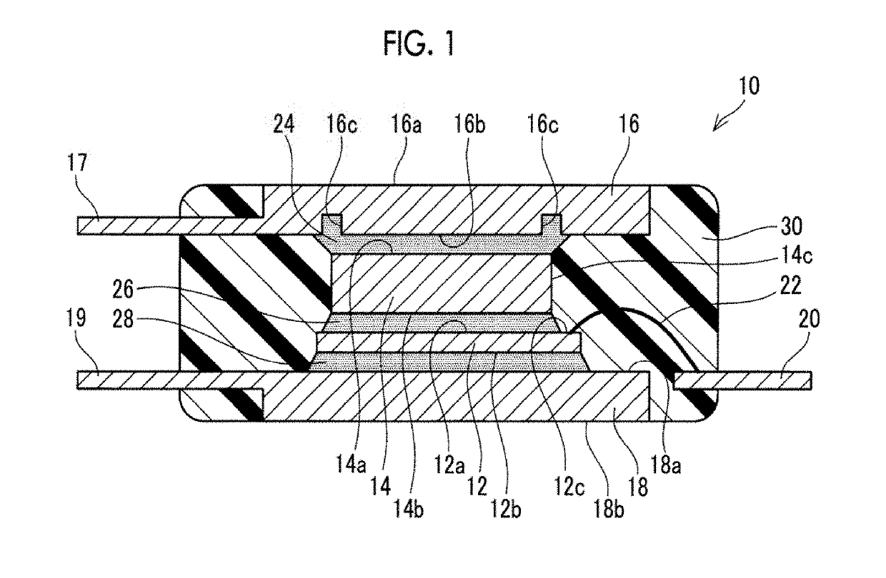
[0035]As illustrated in FIG. 1, the semiconductor device 10 includes a semiconductor element 12, a sealing body 30, and a plurality of external connection terminals 17, 19, 20. The semiconductor element 12 is sealed inside the sealing body 30. The sealing body 30 is not particularly limited, but is formed of, for example, a thermosetting resin such as an epoxy resin. Each of the external connection terminals extends from the outside to the inside ...


PUM


Abstract

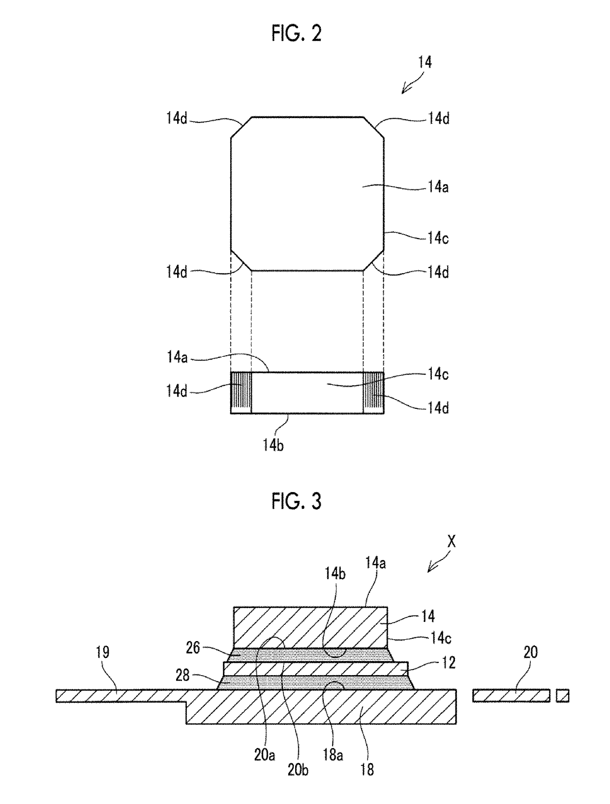
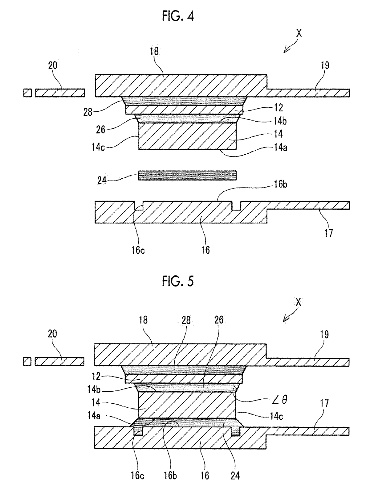
A semiconductor device includes a semiconductor element, a first conductor bonded to an upper surface of the semiconductor element via a first solder layer, and a second conductor bonded to an upper surface of the first conductor via a second solder layer. The first conductor includes at least one groove formed in a stacking direction of the semiconductor element, the first conductor, and the second conductor on a side surface adjacent to the upper surface of the first conductor.

Description

INCORPORATION BY REFERENCE[0001]The disclosure of Japanese Patent Application No. 2018-009950 filed on Jan. 24, 2018 including the specification, drawings and abstract is incorporated herein by reference in its entirety.BACKGROUND1. Technical Field[0002]The present disclosure relates to a semiconductor device and a method of manufacturing the same.2. Description of Related Art[0003]Japanese Unexamined Patent Application Publication No. 2005-136018 (JP 2005-136018 A) discloses a semiconductor device. The semiconductor device includes a semiconductor element, a first conductor bonded to an upper surface of the semiconductor element via a solder layer, and a second conductor bonded to an upper surface of the first conductor via a solder layer. In the semiconductor device, a groove surrounding the solder layer is formed on a lower surface of the second conductor, and excessive solder is accommodated inside the groove. With such a configuration, when the first conductor and the second co...

Claims


Application Information

Patent Timeline
IPC IPC(8): H01L23/492H01L23/42H01L23/00
CPCH01L23/492H01L23/42H01L24/32H01L24/33H01L24/83H01L23/36H01L2224/48247H01L2224/48091H01L2224/32245H01L2224/33181H01L2224/83385H01L2224/73265H01L2224/83101H01L2224/26175H01L23/49568H01L23/49562H01L23/49541H01L23/49548H01L2924/00014H01L24/48H01L2224/92247H01L2924/13055H01L2924/13091H01L2924/10253H01L2924/10272H01L2924/1033H01L2224/05624H01L2224/83447H01L2224/29101H01L2224/83801H01L24/73H01L24/92H01L2224/2612H01L2924/00012H01L2224/45099H01L2224/48257H01L2924/014H01L2924/00
Inventor HATASA, KEITATAKEDA, HIROYUKITAKAHAGI, SATOSHI
Owner DENSO CORP
Learn More