Chain clamp

a chain and clamping technology, applied in the direction of mechanical devices, machine supports, fastening means, etc., can solve the problems of high flexing, laborious wrapping of the ring mount, and high production costs, and achieve the effect of robust performance and convenient setting up

Active Publication Date: 2019-08-01
CUE DEE
View PDF23 Cites 4 Cited by
  • Summary
  • Abstract
  • Description
  • Claims
  • Application Information

AI Technical Summary

Benefits of technology

[0009]It is an object of the present invention to propose a solution for or a reduction of the problems of the prior art. A main object is consequently to propose an improved mounting product, for th

Problems solved by technology

A problem with the prior art designs is that some of them are quite convoluted which makes them expensive to produce and also awkward to mount.
Further, the ring mount has to be mounted to a supporting structure by turning a lot of nuts.
Also, due to the rigidity of the threaded bolts, it can be quite laborious to wrap the ring mount around a supporting structure; at least two threaded bolts have to to be disengaged from one of the metal plates and the remaining threaded bolts do not allow flexing t

Method used


Image

  • Chain clamp
  • Chain clamp
  • Chain clamp

Examples


Embodiment Construction

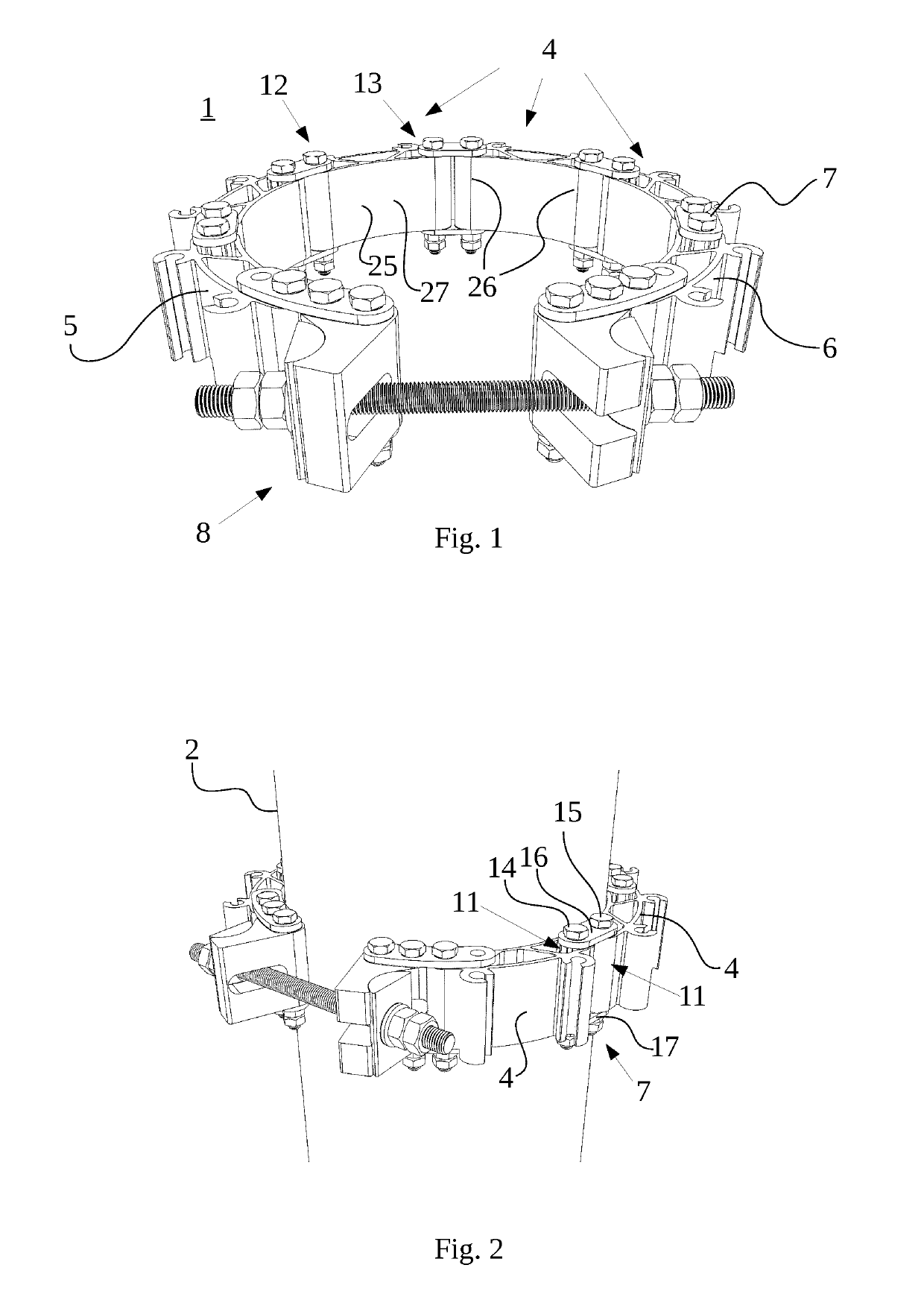
[0026]FIG. 1 depicts a chain clamp 1 according to the invention. The chain clamp 1 is devised for mounting equipment, e.g. telecommunications equipment, to elongated objects such as masts and poles in a quick manner and to avoid the drilling of holes in those elongated objects. This is accomplished by clamping the chain clamp around the elongated object and fastening the telecommunications equipment to the chain clamp.

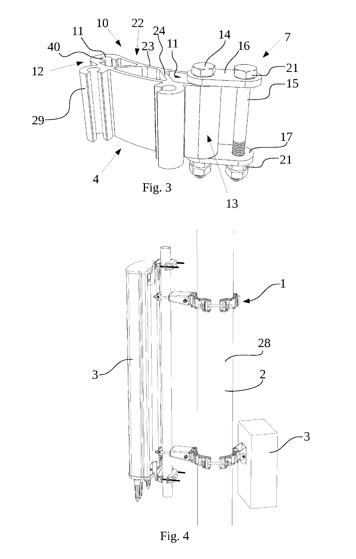
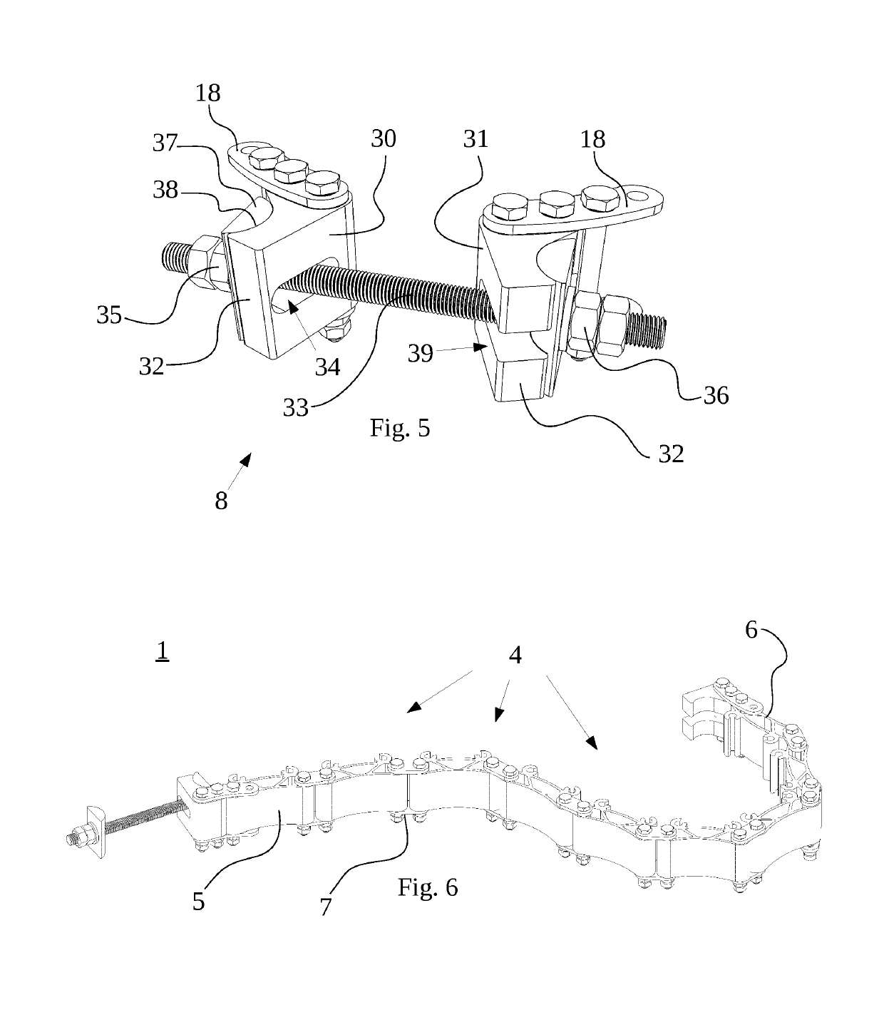
[0027]The chain clamp 1 comprises a plurality of links 4 held together with connection member(s) 7 to form a chain. The plurality of links 4 comprises a minimum of two links. i.e., at least a first link 5 and a second link 6. Each link 4 has two attachment portions 11, one at one end 12 of the link 4 and another at an opposite end 13 of the link 4 (see FIG. 3). There is at least one connection member 7, connecting two different links 4 at their respective attachment portion 11 and keeping them together in the fashion of a chain such that they can rotate in relation to ...


PUM

PropertyMeasurementUnit
Tensionaaaaaaaaaa

Abstract

Chain clamp and method for clamping around an elongated object and for serving as a support for separate objects. The chain clamp includes a plurality of links with a first link and a second link, and with each link having two attachment portions, a connection member connecting links, and a tensioner adapted to connect to the first and second link and to force the links towards each other to tension the chain clamp and clamp it around the elongated object. At least one link is a piece cut from an elongated extrusion and has a fixed cross-sectional profile and a longitudinal direction, wherein each of the two attachment portions of the at least one link are defined by a respective portion of the cross sectional profile and its continuation along the longitudinal direction of the at least one link.

Description

TECHNICAL FIELD[0001]The invention concerns a chain clamp according to the preamble of claim 1. It also concerns a method for producing a chain clamp according to the preamble of claim 11 and a chain clamp as obtainable by such a method.BACKGROUND ARTIntroduction[0002]The proliferation of mobile communications, and also point-to-point radio communications, has led to the use of tall support structures for the mounting of telecommunications equipment, such as radio antennas, in order to improve the reach of such equipment. The support structure may for instance be a pole, mast or a tower. The mounting of telecommunications equipment on to such support structures necessitates some kind of mounting device that can be attached to the support structure and which further provides a means for attaching the telecommunications equipment to the mounting device itself. The mounting device should preferably accommodate different diameters of the support structure, be easy to install, have low w...

Claims


Application Information

Patent Timeline
IPC IPC(8): H01Q1/12B29C48/11B29C48/12F16M13/02F16G13/18H01Q1/24
CPCH01Q1/1228B29C48/11B29C48/12F16M13/02F16G13/18H01Q1/246F16G3/006F16B2/065
Inventor HEMMERVALL, JAN-OLOFPETTERSSON, PATRIK
Owner CUE DEE
Why Eureka
Try Eureka