The performance of the battery system is dependent on the performance of each of the individual battery cells: if one
battery cell suffers from poor performance, the performance of the overall battery system is negatively impacted.
Moreover, if one
battery cell suffers from a fault, other battery cells, the battery system, and / or the system it is powering may be damaged.
As the
energy storage capacity of such battery systems increases, the number of electric battery cells becomes quite large.
While isolators and wires provide a degree of safety, such battery systems suffer from at least the following issues: isolation circuits connected to the
bus can fail and cause a safety fault; isolation circuits and the additional wiring and the additional connectors add cost; the additional wiring and associated connectors are susceptible to fracture from mechanical fatigue; insulation may rub off the wires due to vibration and cause
short circuit faults; communication to the CMCs requires direct connection to the
bus lines; unsecured communication signals present on the
bus will radiate energy which may be detected by unauthorized users and thereby present a security
threat; isolated bus communication can require messages to be passed serially between CMCs until reaching an endpoint and can thereby reduce the overall system bandwidth.
Specifically, because of the large number of battery modules and associated CMCs and wireless communication transceivers in the battery system 100, even occasional faults in the wireless communications between system elements will negatively
impact overall system reliability.
Indeed, communication reliability can be a critical component of a battery system since lack of monitoring information can require issuance of a preemptive safety fault resulting in a shutdown of the battery system and significant
end user impact.
The reflections can cause multipath
fading as well as inter-symbol-interference (ISI).
Multipath
fading results in some locations within the battery system housing having the received RF power drop to zero or close to zero due to deconstructive interference between reflected signals.
At these locations, certain communication links may be unattainable, unreliable, or of
poor quality.
However, since the mechanical dimensions of the battery system housing change over temperature and with vibration (as well as with any other deformation of the container), the channel that works at one instant in time in one location is not guaranteed to work for all instances in time at the one location.
Specifically, the
delay in timing of the artifact in samples from two different CMCs increases with the distance between the associated battery modules in the series stack.
However, if the devices are spatially separated, there will be a
propagation time associated with both directions, which will not be canceled.
We note here that techniques that help combat channel-impairments such as multipath
fading and ISI will not, in general, provide improved timing resolution since these techniques are transparent to a pure propagation-time
delay: time
delay is unobservable using simply these techniques.
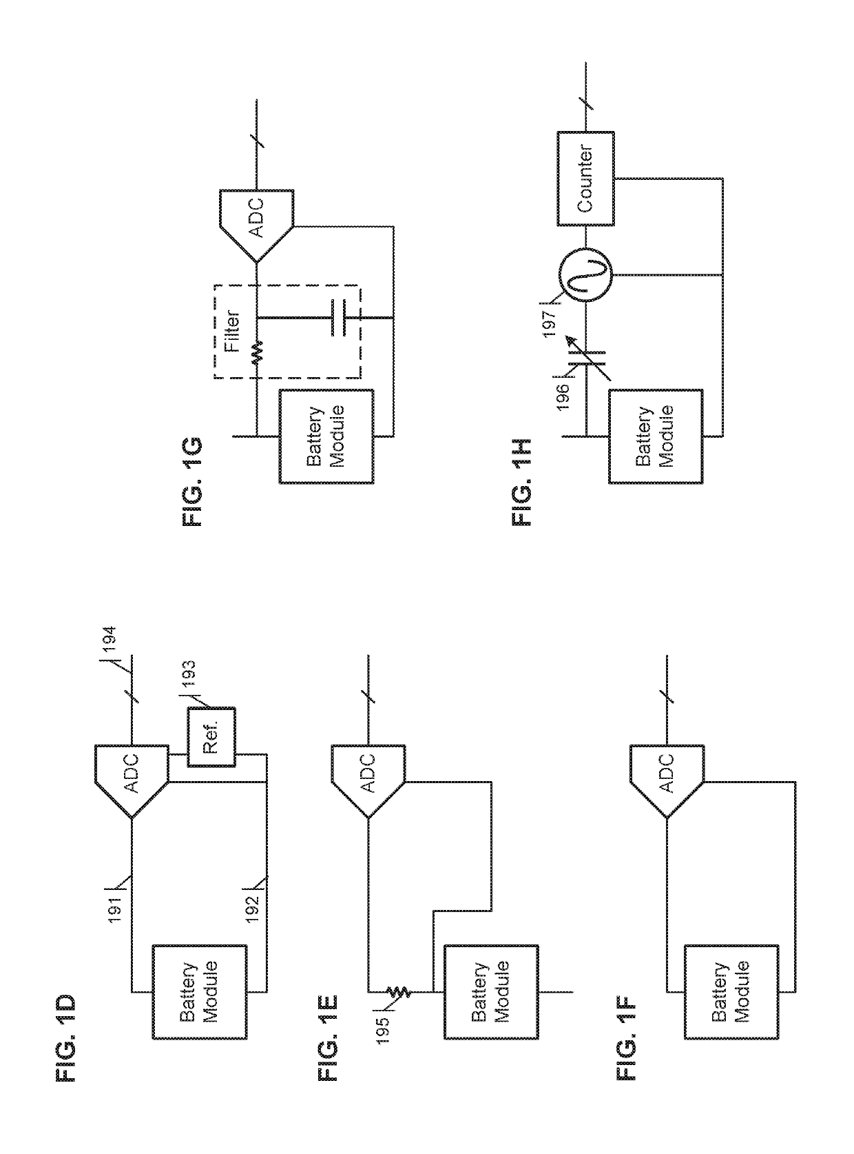
If group delay variation between various ADCs (including any pre-ADC opamps / filters etc.) is non-negligible, this would add directly to
timing error.
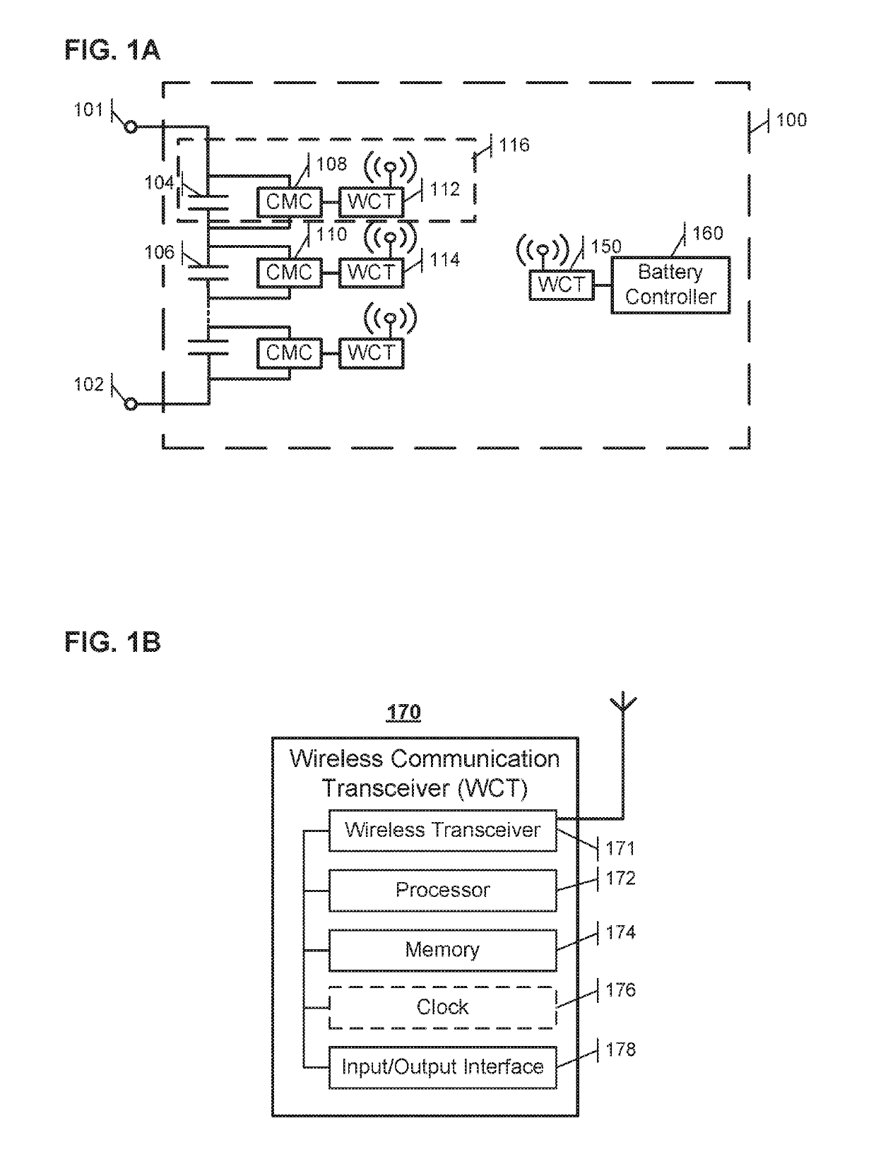
In some embodiments, a fault condition occurs when a WCT does not report information to the battery
system controller within a predetermined expected amount of time or time period.
In this case, a fault is asserted when no data is received from a WCT during the time period, resulting in an action at both sides of the broken
communication link.

