Apparatus and method for heating pipes made of thermoplastic material

Active Publication Date: 2019-08-15
SICA SPA
View PDF9 Cites 0 Cited by
  • Summary
  • Abstract
  • Description
  • Claims
  • Application Information

AI Technical Summary

Benefits of technology

[0036]Another aim of the invention is to provide an apparatus for heating pipes made of thermoplas

Problems solved by technology

The pipes of these systems are small in diameter, normally from 32 mm up to 160 mm and short in length, normally from 0.15 m to 3 m. Compared with PVC-U pipes, the belling techniques of PP and HDPE pipes are different and more complex.
With temperatures which are too low the plastic deformability of the material can be insufficient to form the shape of the bell, or, even if it can be formed, the resulting bell is subject to shrinkage phenomena due to the memory of the initial dimensions of the pipe, the shrinkage effects increasing the greater is the elastic part of the deformation made during the forming step.
Therefore, compared with PVC-U pipes, the most common belling processes applied to PP and HDPE pipes require a temperature distribution along the axis of the pipe, in the circumference and in the thickness of the wall which is almost uniform, as with different temperatures in various zones of the pipe there would be a different behaviour with the shrinkage of the various zones of the bell and, consequently, an unacceptable distortion in shape and a dimensional instability of the bell.
Whilst it is relatively simple to heat the outer surface of the pipe, for example with half-shells which close on the pipe, it is much more complex to achieve a heating by contact of the inner surface.
Mor

Method used


Image

  • Apparatus and method for heating pipes made of thermoplastic material
  • Apparatus and method for heating pipes made of thermoplastic material
  • Apparatus and method for heating pipes made of thermoplastic material

Examples


Example

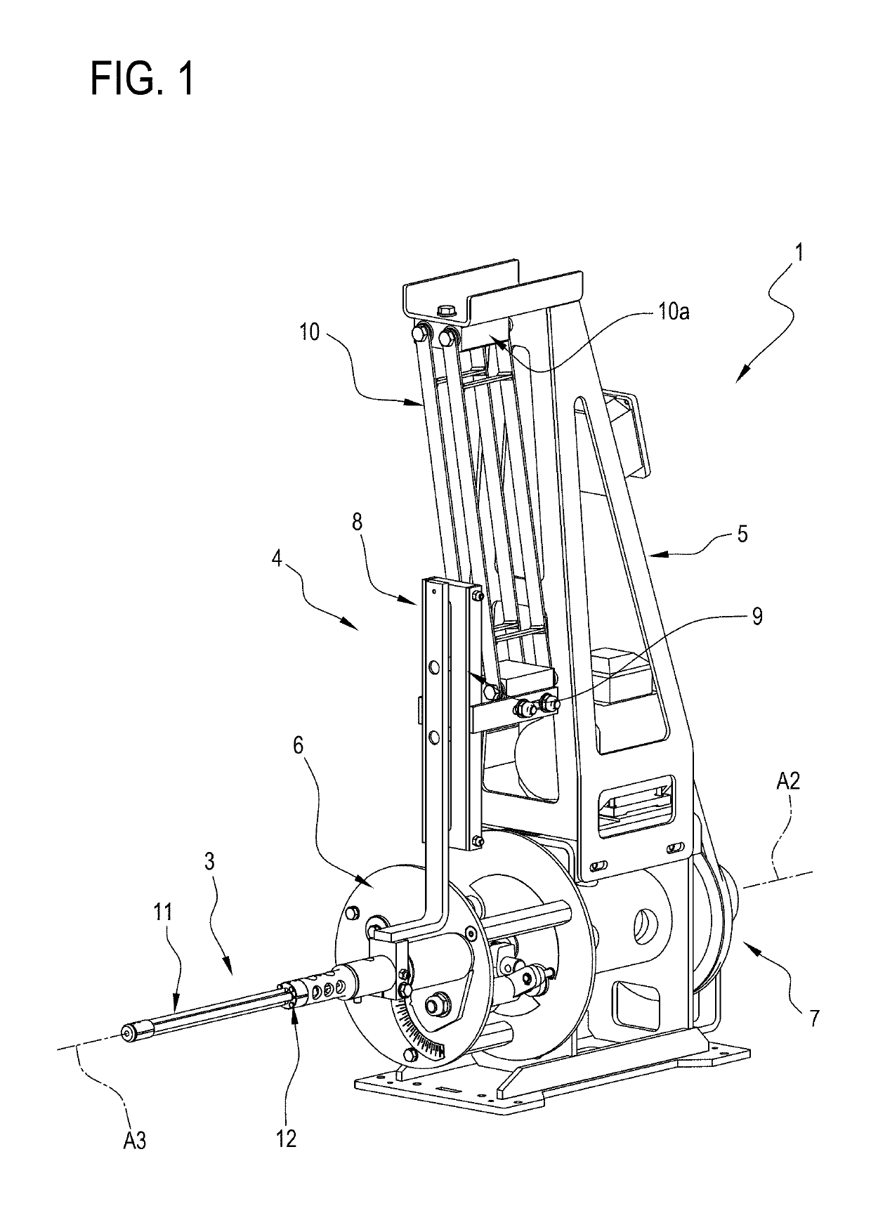
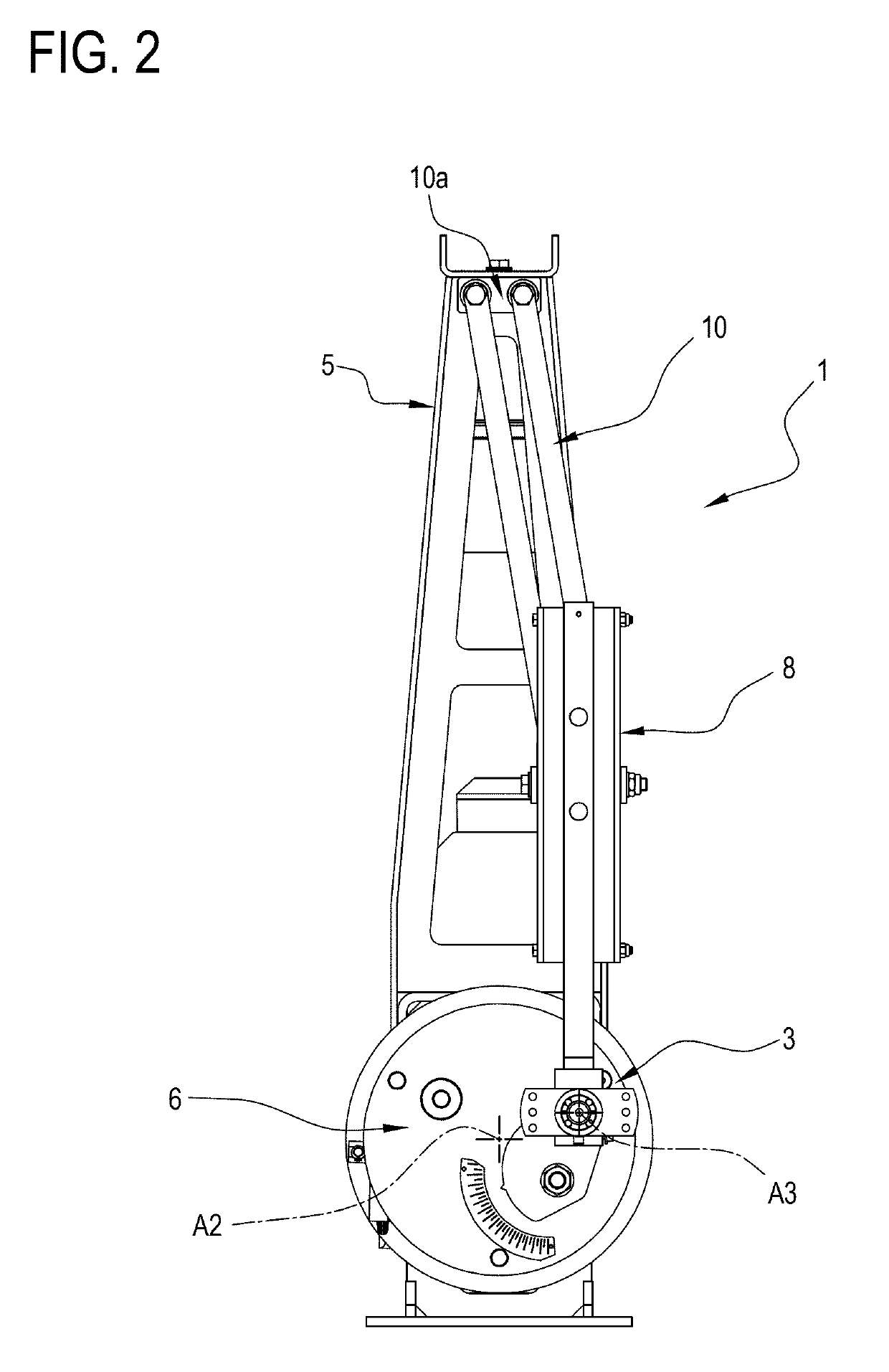
[0047]As illustrated in FIG. 1, the numeral 1 denotes in its entirety a preferred embodiment of the apparatus for heating inside pipes 2 made of thermoplastic material according to this invention.

[0048]The apparatus 1 illustrated in FIG. 1 is designed for heating a single pipe 2 made of thermoplastic material.

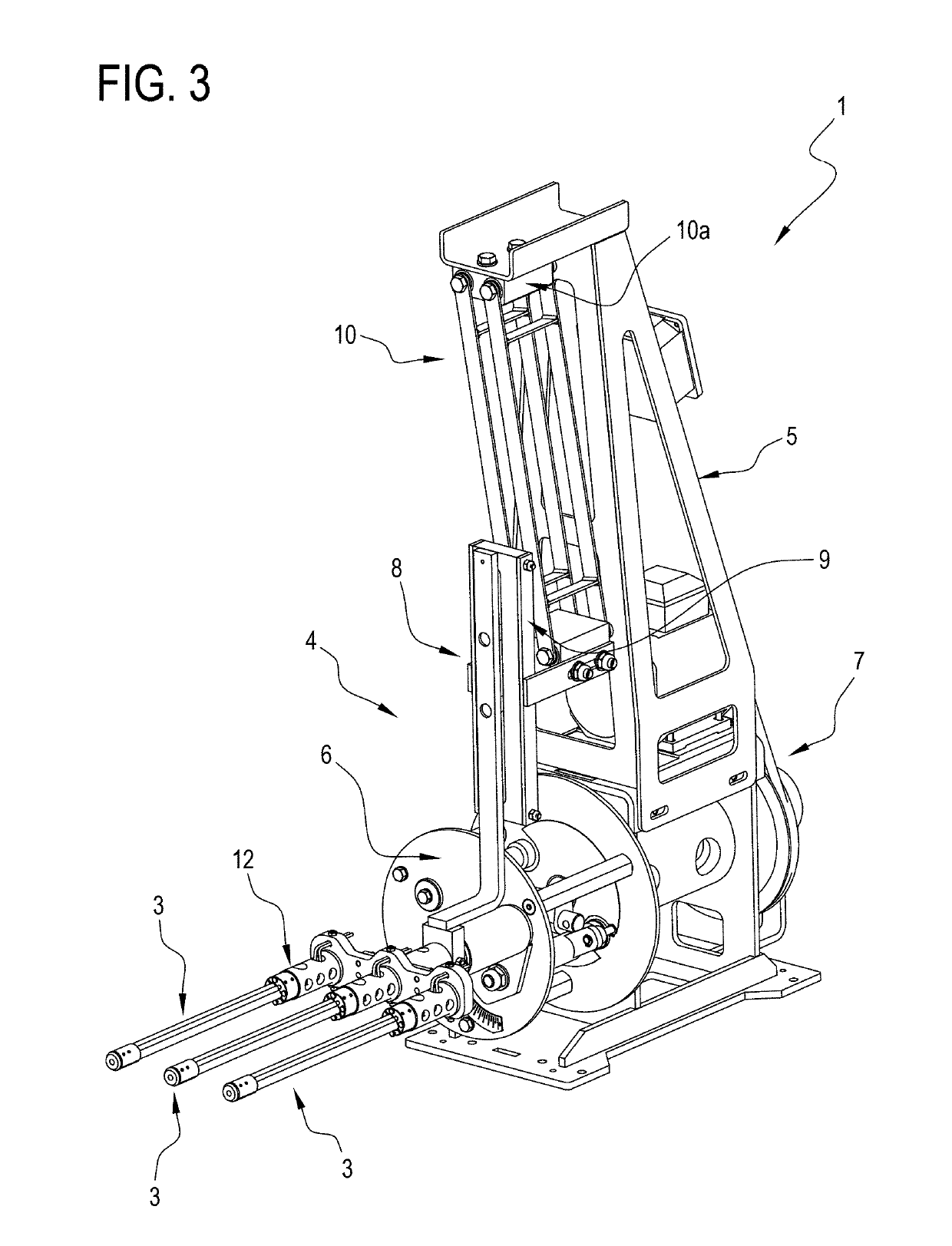
[0049]FIGS. 3 to 6 refer to a variant embodiment of the apparatus 1, designed for the simultaneous heating of a plurality of pipes 2; more specifically, as illustrated by way of example in FIG. 5, the apparatus 1 is designed for the heating of a group of three pipes 2 alongside each other in a horizontal direction.

[0050]More specifically, also as illustrated schematically in FIG. 9, the apparatus 1 comprises a heating element 3, described in more detail below, designed to be inserted partly inside an end portion 2a of a pipe 2 made of thermoplastic material for heating an inner cylindrical surface 2c of the portion 2a.

[0051]The end portion 2a of the pipe 2 is heated for being ...


PUM

PropertyMeasurementUnit
Angleaaaaaaaaaa
Angleaaaaaaaaaa

Abstract

An apparatus for internal heating of end portions of pipes made of thermoplastic material having a central axis including a heating element, designed to be inserted at least partially inside an end portion of a pipe made of thermoplastic material for heating an inner cylindrical surface of the portion, the heating element including an infra-red radiation unit designed to face at least partially the inner cylindrical surface.

Description

TECHNICAL FIELD[0001]This invention relates to an apparatus for heating pipes made of thermoplastic material.[0002]This invention also relates to a method for heating pipes made of thermoplastic material.[0003]More specifically, this invention relates to an apparatus for heating ends of pipes made of thermoplastic material to subject the ends to a subsequent hot plastic deformation process.BACKGROUND ART[0004]The apparatus is especially suitable for performing the step of heating the end of the pipe in the belling process. In effect, in the production of pipes by thermoplastic extrusion designed for making conduits for delivering and / or discharging fluids (used for example in the drainage networks, drinking water distribution networks and sewers of building works), the belling machines are used for forming an end portion of the pipes into the characteristic “bell” shape. This particular wider shape is used to connect the pipes in succession which form a conduit. An unshaped end of a...

Claims


Application Information

Patent Timeline
IPC IPC(8): B29C35/08
CPCB29C35/0805B29C57/02B29C2035/0822B29K2701/12B29L2023/22
Inventor TABANELLI, GIORGIO
Owner SICA SPA
Why Eureka
Try Eureka