Antenna device for vehicle

a technology for vehicles and antennas, applied in individual energised antenna arrays, resonant antennas, particular array feeding systems, etc., can solve the problems of 0, 9 dbi, and cannot meet the specifications required for v2x communication, and achieve the effect of reducing manufacturing costs and high gain

Active Publication Date: 2019-09-05
YOKOWO CO LTD
View PDF5 Cites 4 Cited by
  • Summary
  • Abstract
  • Description
  • Claims
  • Application Information

AI Technical Summary

Benefits of technology

[0024]According to the antenna device for vehicle of the present invention, since the dipole antenna array and the t

Problems solved by technology

Like this, the monopole antenna (in the case where the monopole antenna is installed vertically on a circular ground plate having a diameter of 1 m, the average gain of vertical polarized wave is about −0.9 dBi) has the disadvantage that when the monopole antenna is installed on the roof of a vehicle body or the like, it cannot satis

Method used


Image

  • Antenna device for vehicle
  • Antenna device for vehicle
  • Antenna device for vehicle

Examples


first embodiment

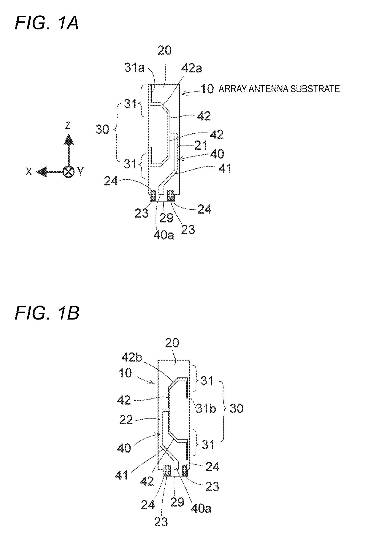
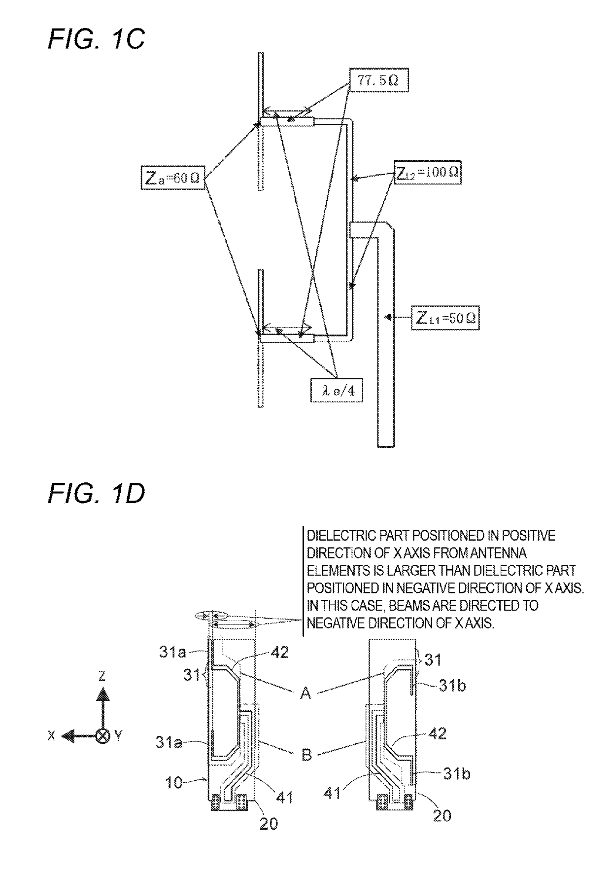
[0100]FIGS. 1A and 1B uses stepwise impedance conversion and the like on the basis of the impedance matching method of FIG. 1C.

[0101]In the first embodiment, in the case of feeding power to the power feeding parts 40a of the two parallel transmission lines 40 via balanced lines, the two parallel transmission lines 40 perform a balanced power feeding operation to excite the dipole antennae 31. Meanwhile, in the case where power feeding to the power feeding part 40a of the two parallel transmission lines 40 via unbalanced lines is performed, the impedance characteristic of the two parallel lines of the common transmission line parts 41 which are unbranched transmission line parts is set to be small (in the present embodiment, the impedance characteristic of the two parallel lines is set to 50Ω) such that even though power feeding via unbalanced lines is performed, in the two parallel lines, a balanced operation becomes dominant. As a result, with respect to the power feeding parts 40a...

second embodiment

[0126] since the wave directors 35 are disposed in parallel with the individual dipole antennae 31, respectively, it is possible to cause directivity on the side where the wave directors 35 are disposed, thereby increasing the gain in the directivity direction. For example, if the array antenna substrate 10A is mounted on the base 15 of FIG. 6 such that the wave directors 35 are positioned on the front side, it has directivity in which high gain is obtained in the traveling direction of the automobile.

[0127]In the second embodiment, the configuration in which the wave directors 35 are provided on the first surface has been described; however, wave directors 35 may be provided on the second surface, or wave directors 35 may be provided on both of the first surface and the second surface.

[0128]FIG. 12A and FIG. 12B show an array antenna substrate 10B according to a third embodiment in the case of configuring a linear polarized wave array antenna device for vehicle as an antenna device...

third embodiment

[0133] since the reflectors 36 are disposed in parallel with the individual dipole antennae 31, respectively, it is possible to cause directivity on the opposite side to the side where the reflectors 36 are disposed, thereby increasing the gain in the directivity direction. For example, if the array antenna substrate 10A is mounted on the base 15 of FIG. 6 such that the reflectors 36 are positioned on the front side, it has directivity in which high gain is obtained on the opposite side to the traveling direction of the automobile.

[0134]In the third embodiment, the configuration in which the reflectors 36 are provided on the first surface has been described; however, reflectors 36 may be provided on the second surface, or reflectors 36 may be provided on both of the first surface and the second surface.

[0135]FIG. 17A and FIG. 17B show an array antenna substrate 10C according to a fourth embodiment in the case of configuring a linear polarized wave array antenna device for vehicle as...


PUM


Abstract

Provided is a linear polarization array antenna device for vehicle that is low-cost and has a high gain, by forming an array antenna and a transmission line by conductor patterns on a substrate. The present invention is provided with: a dipole antenna array in which a plurality of dipole antennas formed by the conductor patterns provided on a dielectric substrate are arranged; and two parallel transmission lines formed by the conductor patterns provided on the dielectric substrate, wherein power is supplied to the dipole antennas via the transmission lines. The two parallel transmission lines have a structure in which a pair of conductor patterns face each other across the dielectric substrate interposed between the pair of the conductor patterns.

Description

TECHNICAL FIELD[0001]The present invention relates to an antenna device for vehicle which is mounted on a vehicle and is used for V2X (Vehicle to X; Vehicle to Everything) communication (such as vehicle-to-vehicle communication and vehicle-to-roadside communication) and so on.BACKGROUND ART[0002]In the past, monopole antennae and sleeve antennae have been considered as V2X antennae. In FIG. 22 to FIG. 26, the configuration, VSWR (Voltage Standing Wave Ratio), and gain in horizontal plane (X-Y plane) of a monopole antenna are shown, and in FIGS. 27A and 27B to FIG. 31, the configuration, VSWR, and gain in horizontal plane of a sleeve antenna are shown.[0003]With reference to FIG. 22 to FIG. 26, a monopole antenna will be described. FIG. 22 shows the case where a monopole antenna 1 is installed vertically on a circular ground plate 5 (a circular conductor plate having a diameter of 1 m), and as shown in FIG. 23, the VSWR in this case is 1.4209 at a frequency of 5850 MHz, and is 1.4076...

Claims


Application Information

Patent Timeline
IPC IPC(8): H01Q1/32H01Q9/16H01Q1/38H01Q21/06H01Q1/42H01Q19/10
CPCH01Q1/32H01Q9/16H01Q19/10H01Q21/06H01Q1/42H01Q1/38H01Q1/3216H01Q1/50H01Q9/26H01Q21/0006H01Q21/062H01Q1/1214H01Q1/3275H01Q21/08H01Q19/30H01Q9/065H01Q21/205H01Q19/24
Inventor SONE, TAKAYUKI
Owner YOKOWO CO LTD
Why Eureka
Try Eureka