Method and apparatus for artifact reduction for joint region in step and shoot computed tomography

a computed tomography and joint region technology, applied in the field of diagnostic imaging, can solve problems such as image artifacts, insufficient data, and inability to reduce artifacts for joint regions in step and shoot computed tomography systems, and achieve the effect of improving ccb scans

Inactive Publication Date: 2019-09-12
MINFOUND MEDICAL SYST CO LTD
View PDF0 Cites 0 Cited by
  • Summary
  • Abstract
  • Description
  • Claims
  • Application Information

AI Technical Summary

Problems solved by technology

X-rays passing through the patient can cause x-ray scatter to occur, which can cause image artifacts.
However, a fundamental circular cone beam (CCB) scan suffers from cone beam artifacts due to data incompletion, (i.e. projection data does not satisfy a data sufficiency condition (DSC)).
That is, CCB data fundamentally includes insufficient data and there is thus no stable reconstruction.
Unfortunately, some regions at the ends of the volume do not satisfy this condition even for a full circular, 360-degree scan, and the largest region that can be reconstructed contains the voxels having 180 degrees plus fan angle projection data.
If a reconstruction volume z-coverage is set to the full illumination range at z-axis, some regions at the end slices of the volume do not satisfy this condition either even for a full circular, 360-degree, scan, which can lead to image artifacts.
However, true z-coverage in this method is less than that of the system, and partial radiation dose may be wasted.
However, this computationally costly method may alter noise properties in reconstructed images, and inaccurately extrapolated data may be used to reconstruct the end slices of each scan.
This can result in large errors in the final images, and performance is largely dependent on the weighing strategy, which may include an estimation of the amount of extrapolation used in the reconstruction.

Method used


Image

  • Method and apparatus for artifact reduction for joint region in step and shoot computed tomography
  • Method and apparatus for artifact reduction for joint region in step and shoot computed tomography
  • Method and apparatus for artifact reduction for joint region in step and shoot computed tomography

Examples


experiment 1

[0056] A simulated FORBILD head phantom was projected and then reconstructed with a FOV of 350 mm. This phantom, having a complicated high contrast structure, presents a challenge object and thus it is good for reconstruction performance evaluation. The total number of slices of the reconstructed images is 128 slices with separation 0.625 mm. The end slice of the first rotation, i.e. 64th slice, has high resolution, and not having distortion, black shading, or other artifacts caused by data missing or extrapolation related inaccuracy.

experiment 2

[0057] Abdomen section of human body phantom was scanned with 80 mm shift from iso-center and the body section is reconstructed with FOV 512 mm with 80 mm center shift correspondingly. This experiment demonstrates the feasibility of interpolation between two rotations for regions far from the Z-axis in end slices where the gap has the maximum extent. Again, the total number of slices of the reconstructed images is 128 slices with a separation of 0.625 mm. When the body center has 80 mm offset from the Z-axis, the regions of the abdomen section is more than 200 mm away from z-axis. Thus, there exists a large data gap between two rotations. A corresponding image was obtained, having no distortion, black shading, or other strong artifacts caused by data missing or extrapolation related inaccuracy.

Algorithm 2. SAS reconstruction by weighted re-binning FDK algorithmfrom complementary projection data.Step 1: Re-binning the projection data p(γ,v,β) from fan geometryto parallel geometry for...


PUM


Abstract

A computed tomography (CT) system includes a rotatable gantry having an opening to receive an object to be scanned, an x-ray tube having an anode, the x-ray tube positioned on the gantry to generate x-rays from a focal spot of the anode and through the opening, a pixelated detector positioned on the gantry to receive the x-rays from which CT projection data is generated, and a computer. The computer programmed to acquire step-and-shoot (SAS) full scan CT projection data for a first scan and for a first rotation, and for a second scan and for a second rotation, wherein the first scan is axially offset from the second scan, interpolate across the first and second scans to generate interpolated projection data, and reconstruct an image based on the interpolated projection data.

Description

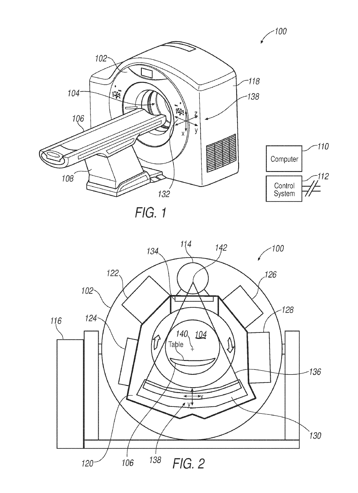
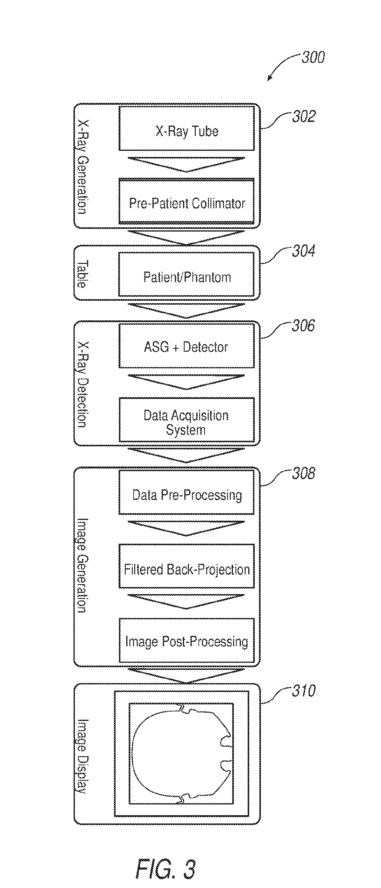
TECHNICAL FIELD[0001]This disclosure relates generally to diagnostic imaging and, more particularly, to an apparatus and method of reducing artifacts for a joint region in a step and shoot computed tomography (CT) system.BACKGROUND[0002]Typically, in computed tomography (CT) imaging systems, a rotatable gantry includes an x-ray tube, detector, data acquisition system (DAS), and other components that rotate about a patient that is positioned at the approximate rotational center of the gantry. X-rays emit from the x-ray tube, are attenuated by the patient, and are received at the detector. The detector typically includes a photodiode-scintillator array of pixelated elements that convert the attenuated x-rays into photons within the scintillator, and then to electrical signals within the photodiode. The electrical signals are digitized and then received within the DAS, processed, and the processed signals are transmitted via a slipring (from the rotational side to the stationary side) ...

Claims


Application Information

Patent Timeline
Patent Type & Authority Applications(United States)
IPC IPC(8): A61B6/00G06T11/00G06T3/40G06T7/00
CPCA61B6/5282G06T2207/10081G06T3/4007G06T7/97G06T7/0012G06T11/005A61B6/032A61B6/4085A61B6/4291A61B6/5205
Inventor GUO, HONGBINMIAO, CHUANGIKHLEF, ABDELAZIZCUI, XUELIN
Owner MINFOUND MEDICAL SYST CO LTD
Why Eureka
Try Eureka