Power amplifier module

a power amplifier and module technology, applied in amplifier protection circuit arrangements, amplifiers with semiconductor devices/discharge tubes, instruments, etc., can solve the problems of excessive current flowing in the power amplifier circuit, limited current flowing through the power amplifier circuit in the transmission unit,

Active Publication Date: 2019-09-12
MURATA MFG CO LTD
View PDF0 Cites 2 Cited by
  • Summary
  • Abstract
  • Description
  • Claims
  • Application Information

AI Technical Summary

Benefits of technology

[0006]The present disclosure has been made in view of such circumstances, and it is an object of the present disclosure to suppress a current flowing through a power amplifier circuit when an input power is equal to or larger than a predetermined threshold value.

Problems solved by technology

Therefore, in order to prevent the power amplifier circuit from being broken due to the large current, the current flowing through the power amplifier circuit is limited in the transmission unit.
WO 2015 / 002294, if the input power increases, the current flowing in the power amplifier circuit may become excessively large due to a self-bias effect.

Method used


Image

  • Power amplifier module
  • Power amplifier module
  • Power amplifier module

Examples


first embodiment

1. Configuration of Power Amplifier Module 1A

1-1. Power Amplifier Module 1A

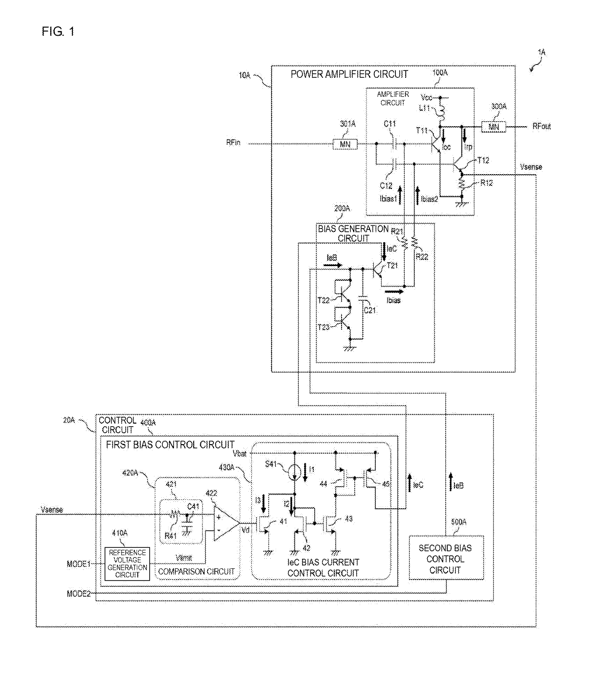
[0025]FIG. 1 is a diagram illustrating an example of a configuration of a power amplifier module 1A according to a first embodiment of the present disclosure. The power amplifier module 1A amplifies a radio frequency (RF) signal RFin and outputs an amplified signal RFout.

[0026]As illustrated in FIG. 1, the power amplifier module 1A includes a power amplifier circuit 10A and a control circuit 20A. The power amplifier circuit 10A and the control circuit 20A are formed on different substrates, for example. For example, the power amplifier circuit 10A may be configured using a bipolar transistor such as a heterojunction bipolar transistor (HBT). When an HBT is used for the power amplifier circuit 10A, for example, SiGe, GaAs, InP, GaN, or the like may be used as a material of a substrate constituting the HBT. Further, the control circuit 20A may be configured using, for example, a metal-oxide-silicon field-effect...

second embodiment

1. Configuration of Power Amplifier Module 1B

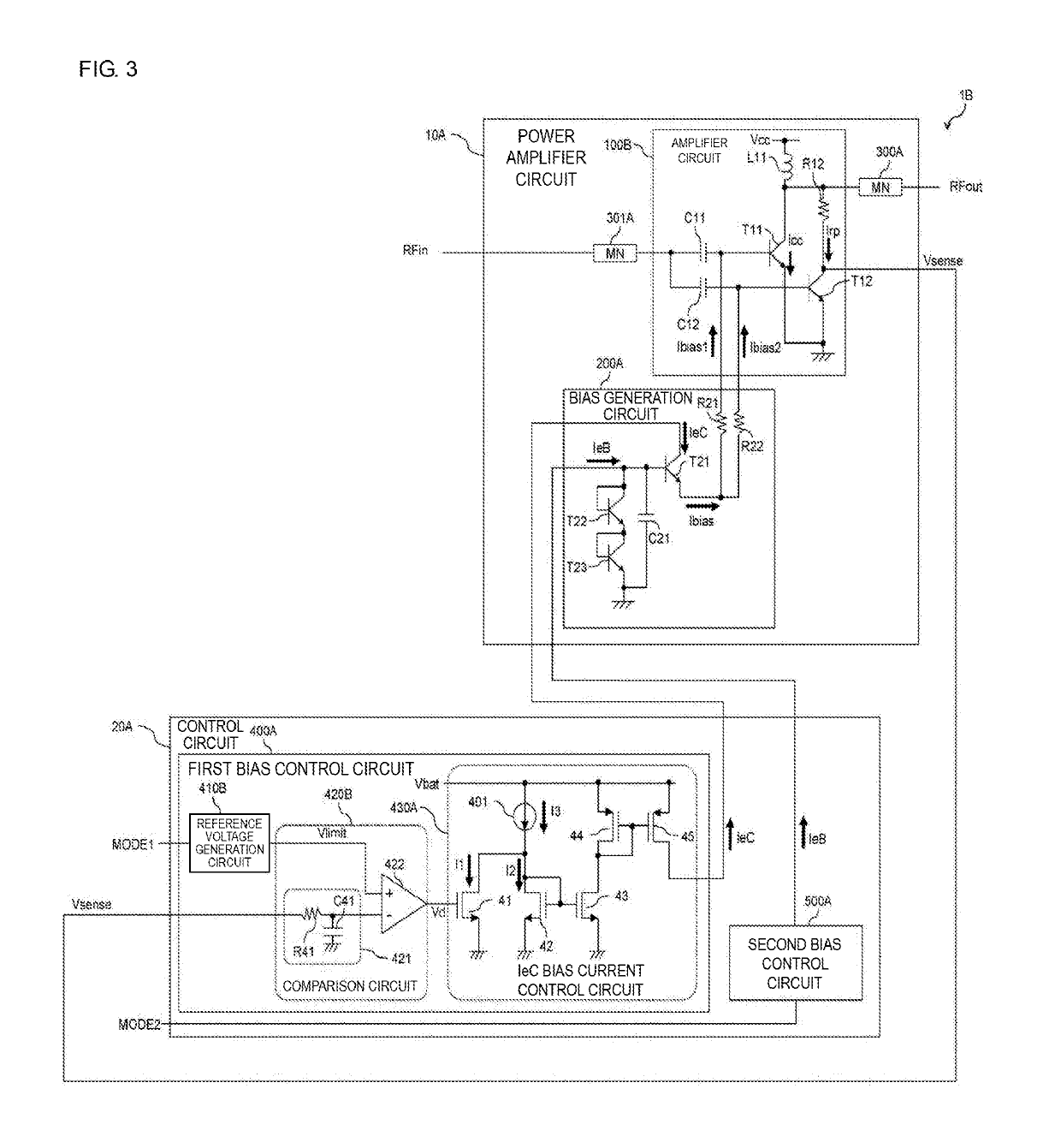
[0061]FIG. 3 is a diagram illustrating an example of a configuration of a power amplifier module 1B according to a second embodiment of the present disclosure. In the configuration of the power amplifier module 1B, the descriptions of the same configuration as that of the power amplifier module 1A will be omitted as appropriate.

[0062]As illustrated in FIG. 3, the power amplifier module 1B includes an amplifier circuit 100B in place of the amplifier circuit 100A. In addition, the power amplifier module 1B includes a comparison circuit 420B instead of the comparison circuit 420A. Moreover, the power amplifier module 1B includes a reference voltage generation circuit 410B instead of the reference voltage generation circuit 410A.

[0063]In the amplifier circuit 100B, the resistor element R12 is connected to the collector side of the transistor T12. In other words, the first terminal of the resistor element R12 is connected to the second termina...

third embodiment

[0075]FIG. 5 is a diagram illustrating an example of a configuration of a power amplifier module 1C according to a third embodiment of the present disclosure. In the configuration of the power amplifier module 1C, the descriptions of the same configurations as that of the power amplifier module 1A will be omitted as appropriate.

[0076]As illustrated in FIG. 5, the power amplifier module 1C includes an amplifier circuit 100C in place of the amplifier circuit 100A. In addition, the control circuit 20A of the power amplifier module 1C further includes a current detection circuit 600C.

[0077]The amplifier circuit 100C does not include the resistor element R12, and includes an inductor L12. A first terminal of the inductor L12 is connected to the current detection circuit 600C included in the control circuit 20A. A second terminal of the inductor L12 is connected to the collector of the transistor T11 and the collector of the transistor T12. In the amplifier circuit 100C, the collector cur...


PUM


Abstract

A power amplifier module includes a first transistor that amplifies and outputs a radio frequency signal, a second transistor smaller in size than the first transistor and connected in parallel with the first transistor, a third transistor that supplies a bias current to the first and second transistors, a current detection circuit that detects a current flowing through a collector of the second transistor, and a bias control circuit that controls the bias current supplied from the third transistor to the first and second transistors by supplying a current corresponding to a detection result of the current detection circuit to a collector or a drain of the third transistor. In a case that a current flowing through the collector of the second transistor is larger than a predetermined threshold value, the bias control circuit reduces the current supplied to the collector or the drain of the third transistor.

Description

[0001]This application claims priority from Japanese Patent Application No. 2018-042878 filed on Mar. 9, 2018, and claims priority from Japanese Patent Application No. 2019-003806 filed on Jan. 11, 2019. The content of these applications are incorporated herein by reference in their entireties.BACKGROUND OF DISCLOSURE1. Field of the Disclosure[0002]The present disclosure relates to a power amplifier module.2. Description of the Related Art[0003]In mobile communication equipment such as a cellular phone, a transmission unit for transmitting a radio frequency (RF) signal to a base station is mounted. A power amplifier circuit for amplifying power of an RF signal to be transmitted to the base station is used in the transmission unit. In such transmission unit, a large current may flow in the power amplifier circuit when, for example, an impedance of a load such as an antenna or the like changes. Therefore, in order to prevent the power amplifier circuit from being broken due to the lar...

Claims


Application Information

Patent Timeline
Patent Type & Authority Applications(United States)
IPC IPC(8): H03F3/24H03F3/193H03F1/52
CPCH03F3/245H03F1/523H03F3/193H03F3/189H03F3/24H03F3/45376H04B1/04H04B2001/0408H03F3/191H03F1/52H03F2200/18H03F1/0272G05F3/262G05F1/561
Inventor MORISAWA, FUMINORIMUKAI, KENJIHONDA, YURI
Owner MURATA MFG CO LTD
Why Eureka
Try Eureka