Bond pattern

a technology of mechanical bonding and bonding pattern, applied in the field of mechanical bonding composites, can solve the problems of fracture at the bonding location, limited amount of glue that can be added to the bonding region, and known bonding pattern not designed to sustain high stress from multiple directions

Active Publication Date: 2019-09-26
THE PROCTER & GAMBLE COMPANY
View PDF10 Cites 2 Cited by
  • Summary
  • Abstract
  • Description
  • Claims
  • Application Information

AI Technical Summary

Problems solved by technology

While such bonds may be strong, the laminate that is created can incur significant stress concentration during product application, which can lead to fracture at the bonded locations.
In particular, known bond patterns are not designed to sustain high stress from multiple directions.
However, there is a limited amount of glue that can be added to a bond region, given the dimensions of the article, the overlap area of the bonded substrates, and other physical constraints.

Method used


Image

  • Bond pattern
  • Bond pattern
  • Bond pattern

Examples


examples

[0053]The following composite examples demonstrate properties of the invention herein.

[0054]The Comparative Example A comprises an initial set of substrates. The initial exemplary set includes a first substrate that is a ring-rolled activated laminate having an elastic film sandwiched between two nonwovens, where one nonwoven comprises a spunbond web and the other nonwoven comprises a carded web. The laminate layers are joined by adhesive. The laminate is commercially available from Clopay, USA under the trade name ELASTIPRO™ 8004. The laminate is bonded to the second substrate in an inelastic region. The second substrate is a cuff-backsheet laminate comprising a 19 gsm polypropylene spunbond nonwoven material, commercially available from Avgol, USA under tradename AVMN1071984001, a 15 gsm polymeric film, commercially available from Clopay, USA under tradename CLNT0045465363, and a 12 gsm SMS polypropylene nonwoven material commercially available from Berry Global under tradename PG...


PUM

PropertyMeasurementUnit
Peel Strengthaaaaaaaaaa
Lateral Peak Peel Strengthaaaaaaaaaa
pressureaaaaaaaaaa

Abstract

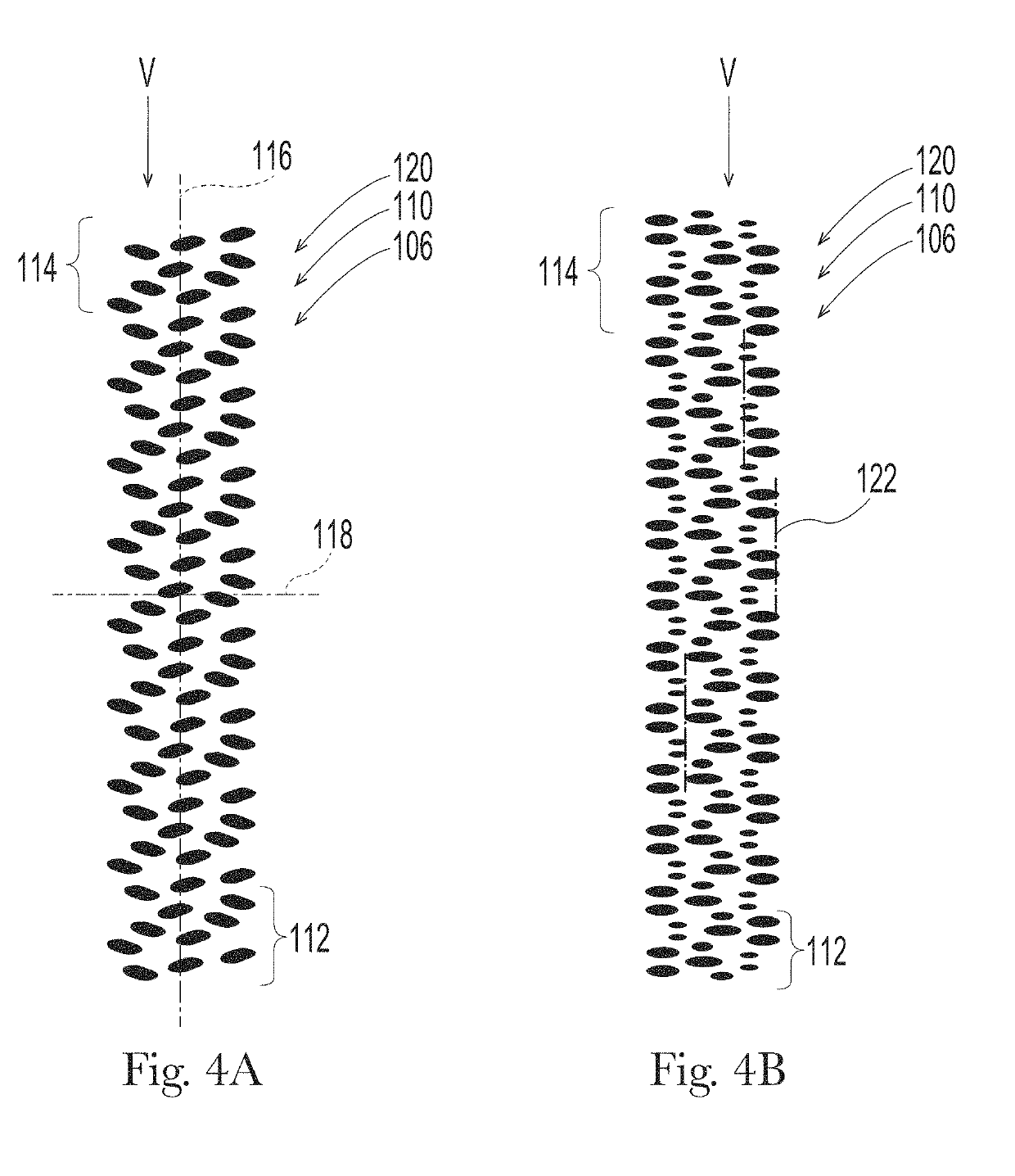
A composite includes a first substrate and a second substrate joined in a bonding region, wherein the first substrate comprises a first Peak Force Tensile Strength and the second Peak Force Tensile Strength. The first Peak Force Tensile Strength is greater than or equal to the second Peak Force Tensile Strength. The bonding region has a Bond Density of about 10% to about 22%; and a Composite Tensile Strength at Peak Force that is within about 15% of the second Peak Force Tensile Strength.

Description

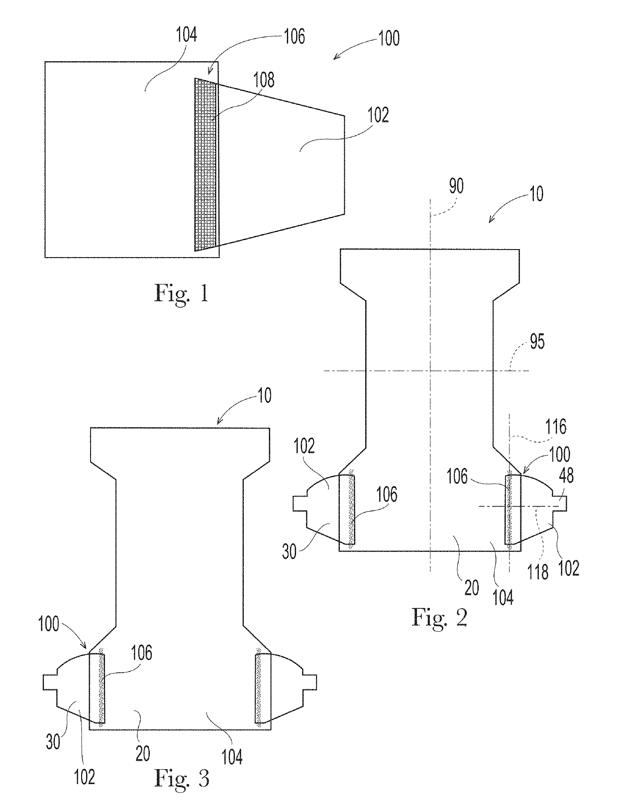
FIELD OF THE INVENTION[0001]The present invention relates to mechanically bonded composites, more specifically mechanically bonded composites that are useful in absorbent articles.BACKGROUND OF THE INVENTION[0002]It has long been known that absorbent articles such as conventional absorbent articles (e.g., diapers, adult incontinence articles, feminine hygiene pads) offer the benefit of receiving and containing urine and / or other bodily exudates (e.g., feces, menses, mixture of feces and urine, mixture of menses and urine, etc.). The assembly of such articles requires joining different components together through various bonding techniques. In doing so, manufacturers must balance bond strength with feel, material costs and processing considerations.[0003]One form of bonding is mechanical bonding, which may be done by high pressure dynamic bonding where the substrates are compressed between an anvil member and the patterned member, as is disclosed in more detail for example in U.S. Pa...

Claims


Application Information

Patent Timeline
Patent Type & Authority Applications(United States)
IPC IPC(8): A61F13/515A61F13/511A61F13/514A61F13/53A61F13/551
CPCA61F13/515A61F13/53A61F2013/51078A61F2013/1591A61F13/514A61F13/55115A61F13/511A61F13/15699A61F13/15756
Inventor DRIA, RAY DENNISPAGE, MICHAEL JOSEPHGROLMES, JOSEPH LESLIEKING, SCOTT ALANRITTER, MATTHEW STEVENARP, CHRISTOPHER COLIN
Owner THE PROCTER & GAMBLE COMPANY
Why Eureka
Try Eureka