Eureka AIR delivers breakthrough ideas for toughest innovation challenges, trusted by R&D personnel around the world.

Directed assembly of nanoparticles with light and electric field

a technology of light and electric field, applied in the field of optical manipulation of nanoscale objects, can solve problems such as particle agglomeration

Active Publication Date: 2019-10-03
VANDERBILT UNIV
View PDF0 Cites 1 Cited by
  • Summary
  • Abstract
  • Description
  • Claims
  • Application Information

AI Technical Summary

Benefits of technology

The patent text is about a way to quickly understand what the technical disclosure is about. It groups together different features in different embodiments to make it easier to read. However, some of the features in the claims are not exact and may require additional features in a single embodiment. The details of the invention can be found in the claims themselves. Overall, the technical effect of this patent is to improve communication and understanding by organizing features in a way that allows R&D personnel to quickly understand the nature of the genomic disclosure.

Problems solved by technology

Among the issues in this area is how to deliver a single suspended particle towards a given plasmonic nanoantenna where it would be trapped by optical gradient forces.
Despite a relatively fast (˜1 μm / s) fluid motion, this technique suffers from the issue of particle agglomeration, which prevents plasmonic trapping of individual nano-objects at a given plasmonic hotspot.
Additionally, a complete and consistent study of any synergistic effect of heat-induced and optical-gradient forces affecting the motion of suspended particles presents theoretical and experimental challenges, and thus has not yet been developed.

Method used


Image

  • Directed assembly of nanoparticles with light and electric field
  • Directed assembly of nanoparticles with light and electric field
  • Directed assembly of nanoparticles with light and electric field

Examples


Embodiment Construction

[0018]In the following description, numerous details are set forth, such as circuit configurations, waveform timings, circuit operations, and the like, in order to provide an understanding of one or more aspects of the present disclosure. It will be readily apparent to one skilled in the art that these specific details are merely exemplary and not intended to limit the scope of this application.

[0019]Overview and ETP Principles

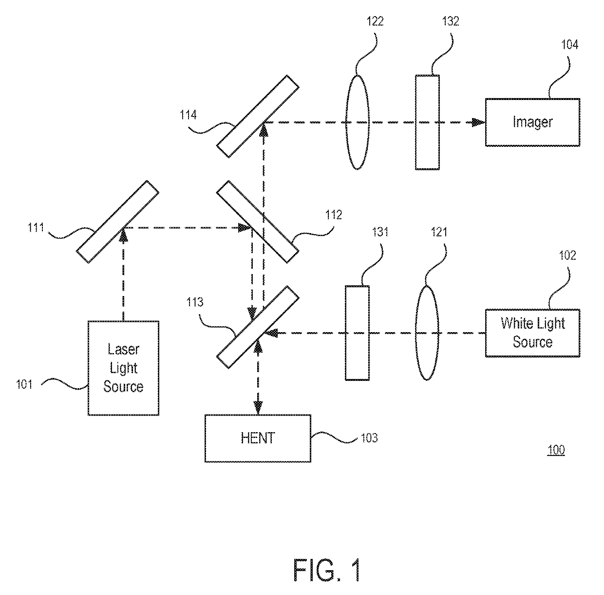
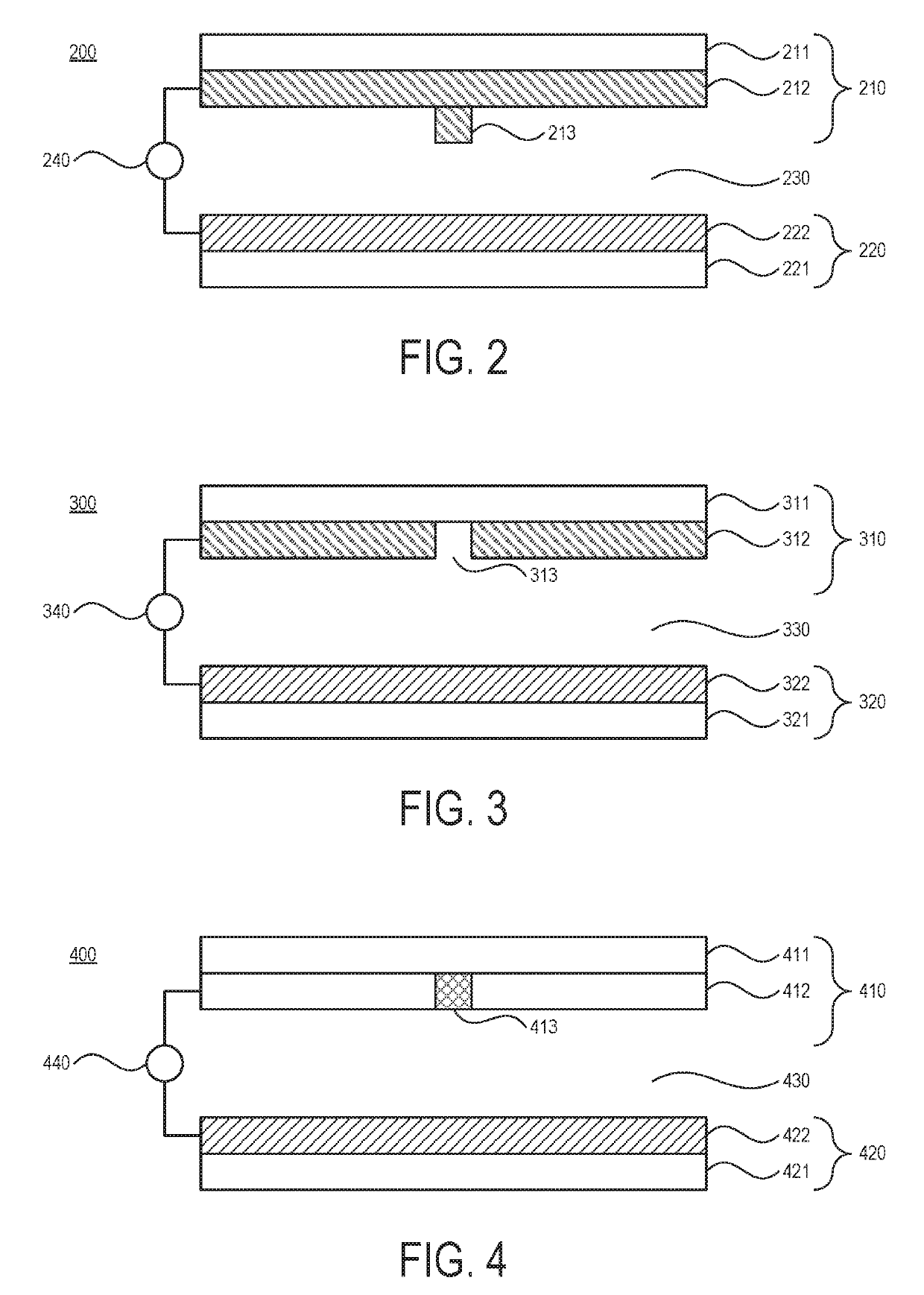
[0020]To resolve the aforementioned issues and realize a nanotweezer capable of rapidly delivering individual nano-objects to a given illuminated nanoantenna on-demand and achieving high-resolution trapping of such objects, without persistent perturbing convection and thermophoretic forces, the present disclosure describes an optofluidic mechanism for generating fluidic transport and particle delivery on-demand by combining the photo-induced heating of a single plasmonic nanoantenna with an alternating current (AC) electric field bias inside of a suspension of...


PUM

PropertyMeasurementUnit
frequencyaaaaaaaaaa
frequencyaaaaaaaaaa
wavelength rangeaaaaaaaaaa

Abstract

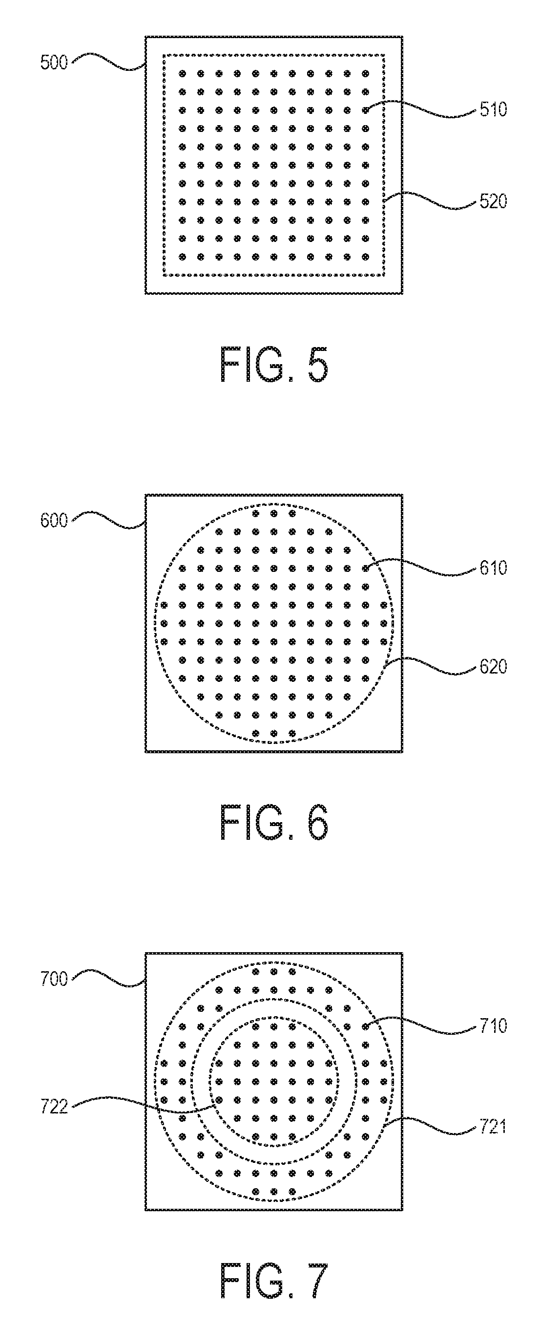
A nanotweezer comprises a first metastructure including a first substrate, a first electrode, and a plurality of plasmonic nanostructures; a second metastructure including a second substrate and a second electrode, wherein the second substrate and the second electrode are substantially transparent to light within a wavelength range; a microfluidic channel between the first metastructure and the second metastructure; a voltage source configured to selectively apply an electric field between the first electrode and the second electrode a light source configured to selectively apply an excitation light to the microfluidic channel, the excitation light having a wavelength within the wavelength range. In response to the selective application of the electric field and / or the excitation light, nanoparticles within the microfluidic channel are manipulated.

Description

CROSS-REFERENCE TO RELATED APPLICATIONS[0001]This application claims priority to U.S. Provisional Application No. 62 / 648,738, filed with the United States Patent and Trademark Office on Mar. 27, 2018, the contents of which are herein incorporated by reference in their entirety.BACKGROUND1. Field of the Disclosure[0002]This application relates generally to the optical manipulation of nanoscale objects. More specifically, this application relates to a hybrid electrothermoplasmonic nanotweezer, and to the long-range and rapid transport of individual nano-objects thereby.2. Description of Related Art[0003]Plasmonic nanoantennas that can create localized and intensified electromagnetic fields have been studied as candidates for the efficient trapping and manipulation of nanoscale objects, which cannot be resolved with diffraction-limited optical tweezers. Among the issues in this area is how to deliver a single suspended particle towards a given plasmonic nanoantenna where it would be tr...

Claims


Application Information

Patent Timeline
Patent Type & Authority Applications(United States)
IPC IPC(8): G02B5/00B81C1/00G01N21/552
CPCG02F2202/30G02B5/008B81C1/00206G01N21/554G02B1/002G02B21/32
Inventor NDUKAIFE, JUSTUS C.
Owner VANDERBILT UNIV
Why Eureka
Eureka Blog
Learn More