Analyzing grid for phase contrast imaging and/or dark-field imaging

a phase contrast and imaging grid technology, applied in imaging devices, instruments, diaphragm/collimeter handling, etc., can solve the problems of poor x-ray dose efficiency and significantly more time required for phase contrast imaging procedures when compared to conventional x-ray applications, and achieve the effect of increasing x-ray dose efficiency

Active Publication Date: 2019-10-03
KONINKLJIJKE PHILIPS NV
View PDF0 Cites 4 Cited by
  • Summary
  • Abstract
  • Description
  • Claims
  • Application Information

AI Technical Summary

Benefits of technology

[0004]Hence, there may be a need to provide an improved grid for phase contrast imaging and / or dark-field imaging, which allows to increase the X-ray dose efficiency during X-ray image acquisition.

Problems solved by technology

Phase contrast imaging procedures therefore require significantly more time when compared to conventional X-ray applications.
Furthermore, the required use of an absorption grid or structured scintillator implies that a considerable amount of X-ray photons passing a patient are discarded, resulting in a poor X-ray dose efficiency.

Method used


Image

  • Analyzing grid for phase contrast imaging and/or dark-field imaging
  • Analyzing grid for phase contrast imaging and/or dark-field imaging
  • Analyzing grid for phase contrast imaging and/or dark-field imaging

Examples


Embodiment Construction

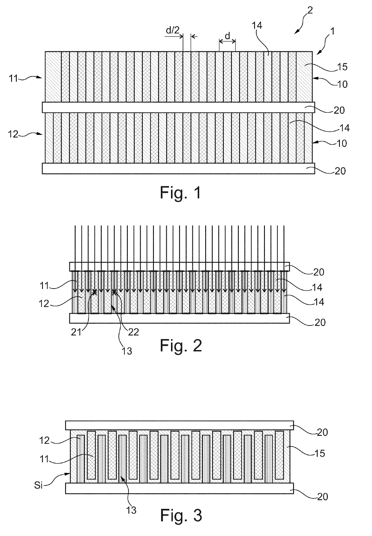
[0054]FIG. 1 shows schematically and exemplarily an embodiment of a detector arrangement for phase contrast imaging and / or dark-field imaging according to the invention. The detector arrangement 2 comprises an analyzing grid 1.

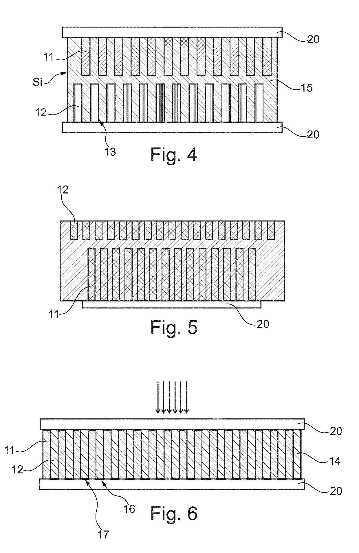
[0055]The analyzing grid 1 comprises here two of X-ray converting gratings 10, namely a first X-ray converting grating 11 and a second X-ray converting grating 12. The X-ray converting gratings 10 convert incident X-ray radiation into light or charge. Here, the X-ray converting grating is a structured scintillator comprising scintillator slabs as grating bars 14.

[0056]The X-ray converting gratings 10 are stacked in a direction parallel to the incident X-ray radiation. The X-ray converting gratings 10 each comprise an array of grating bars 14 made of e.g. CsI. The grating bars 14 are separated by spacers 15 of e.g. silicon.

[0057]The grating bars 14 within each X-ray converting grating are arranged mutually displaced from each other in a direction perpendicular ...


PUM

PropertyMeasurementUnit
transparentaaaaaaaaaa
thicknessaaaaaaaaaa
phase contrast imagingaaaaaaaaaa

Abstract

The invention relates to an analyzing grid for phase contrast imaging and / or dark-field imaging, a detector arrangement for phase contrast imaging and / or dark-field imaging comprising such analyzing grid, an X-ray imaging system comprising such detector arrangement, a method for manufacturing such analyzing grid, a computer program element for controlling such analyzing grid or detector arrangement for performing such method and a computer readable medium having stored such computer program element. The analyzing grid comprises a number of X-ray converting gratings. The X-ray converting gratings are configured to convert incident X-ray radiation into light or charge. The number of X-ray converting gratings comprises at least a first X-ray converting grating and a second X-ray converting grating. Further, the X-ray converting gratings each comprise an array of grating bars, wherein the grating bars within each X-ray converting grating are arranged mutually displaced from each other in a direction perpendicular to the incident X-ray radiation by a specific displacement pitch. Further, the grating bars of the first X-ray converting grating are arranged mutually displaced from the grating bars of the second X-ray converting grating in the direction perpendicular to the incident X-ray radiation by the displacement pitch divided by the number of X-ray converting gratings.

Description

FIELD OF THE INVENTION[0001]The invention relates to an analyzing grid for phase contrast imaging and / or dark-field imaging, a detector arrangement for phase contrast imaging and / or dark-field imaging comprising such analyzing grid, an X-ray imaging system comprising such detector arrangement, a method for manufacturing such analyzing grid, a computer program element for controlling such analyzing grid or detector arrangement for performing such method and a computer readable medium having stored such computer program element.BACKGROUND OF THE INVENTION[0002]X-ray imaging is applied in various technical fields in order to obtain information about internal structures within a region of interest of an object. For example, medical X-ray imaging devices are used to obtain information about internal structures within a patient's body. Phase contrast imaging, e.g. using an interferometer, has been developed to provide higher contrast, especially in soft tissue and other low-absorbing mate...

Claims


Application Information

Patent Timeline
Patent Type & Authority Applications(United States)
IPC IPC(8): G21K1/02G01N23/041A61B6/00
CPCG21K1/025A61B6/4291A61B6/484G21K2207/005G01N23/041A61B6/4035
Inventor KOEHLER, THOMASSTEADMAN BOOKER, ROGERSIMON, MATTHIASRUETTEN, WALTERWIECZOREK, HERFRIED KARL
Owner KONINKLJIJKE PHILIPS NV
Why Eureka
Try Eureka