
Downhole valve for production or injection

a technology for downhole valves and injection wells, applied in the direction of survey, sealing/packing, borehole/well accessories, etc., can solve the problems of complicated wellhead exits, limited downhole valves practicably, and numerous problems of conventional valves

Active Publication Date: 2019-10-17
ORACLE DOWNHOLE SERVICES LTD
View PDF4 Cites 10 Cited by
  • Summary
  • Abstract
  • Description
  • Claims
  • Application Information

AI Technical Summary

Benefits of technology

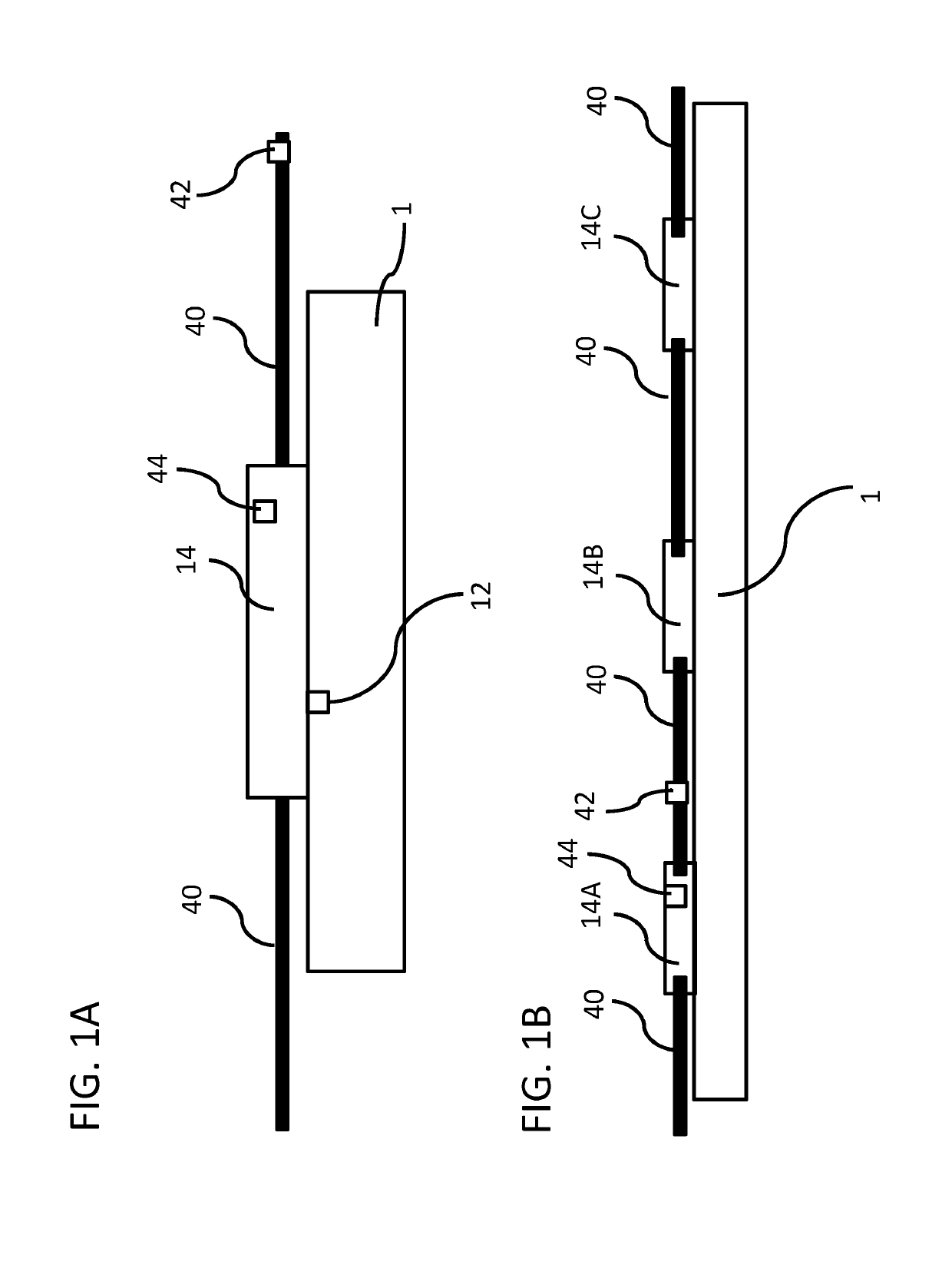
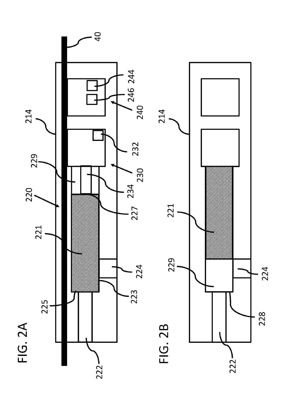
The patent describes a valve assembly that controls fluid flow between two ports. The valve plug can be moved between a closed position and an open position by an electric motor. The valve can be used to control the inflow or outflow of fluid from the valve. The valve can be attached to a tubing sub using brackets, which securely hold the valve assembly in place. The technical effects include the ability to control fluid flow and the use of a special valve design that can be easily attached to a tubing sub.

Problems solved by technology

Conventional valves present numerous problems.
For example, a conventional hydraulic valve requires a separate control line from the wellhead to each downhole valve, which practically limits the number of downhole valves possible.
Another problem includes complicated wellhead exits due to the number of control lines used in a well.
Further, deep wells require increased surface pressure to actuate downhole valves, which becomes a safety hazard.
Still further, if one return line is used for all downhole valves, if it fails, all the lines fail and / or all downhole valves are rendered inoperable.
However, the Manara product uses wellbore pressure to actuate the control valve, which is large and expensive.

Method used


Image

  • Downhole valve for production or injection
  • Downhole valve for production or injection
  • Downhole valve for production or injection

Examples


Embodiment Construction

[0041]Various features and advantageous details are explained more fully with reference to the nonlimiting embodiments that are illustrated in the accompanying drawings and detailed in the following description. Descriptions of well-known starting materials, processing techniques, components, and equipment are omitted so as not to unnecessarily obscure the invention in detail. It should be understood, however, that the detailed description and the specific examples, while indicating embodiments of the invention, are given by way of illustration only, and not by way of limitation. Various substitutions, modifications, additions, and / or rearrangements within the spirit and / or scope of the underlying inventive concept will become apparent to those skilled in the art from this disclosure. The following detailed description does not limit the invention.

[0042]Reference throughout the specification to “one embodiment” or “an embodiment” means that a particular feature, structure, or charac...


PUM


Abstract

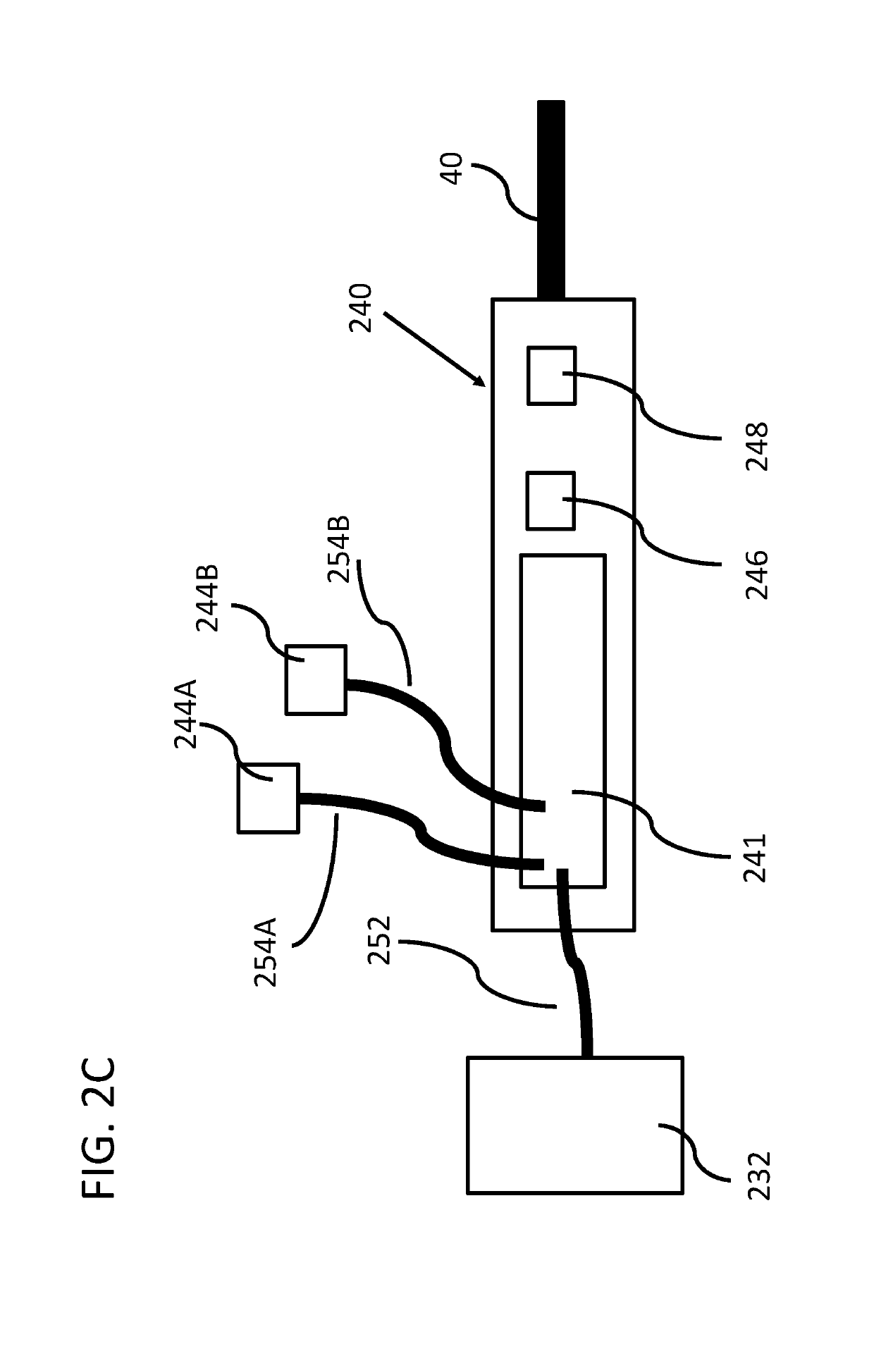
The present disclosure provides a valve assembly comprising a valve section, a power section, and an electronics section. The valve assembly is configured to mate with a tubing sub (and / or mandrel) inserted in-line with a tubing string inserted into a wellbore. The valve allows for injection into or production from the tubing string. The valve assembly comprises an electric motor and a motor controller permitting fine control over the valve, as well as sensors which measure various parameters, such as fluid flow, valve position, pressure, temperature, and / or water cut. A cable connects the valve assembly to the surface and provides power and data telemetry and allows control of the valve assembly with a remote electronic signal. Multiple valve assemblies may be provided at spaced intervals along the tubing string and individually monitored and / or controlled by a remote location. Also disclosed is a method for operation of such valve assemblies.

Description

[0001]This application claims priority to U.S. provisional patent application No. 62 / 657,525, filed on Apr. 13, 2018, the entire content of which is incorporated herein by reference.BACKGROUND OF THE INVENTIONField of the Invention[0002]The present invention relates to a valve for use to produce wellbore fluids in a tubing string and to inject fluids into a wellbore.Description of the Related Art[0003]In the oil and gas industry, downhole valves are used as part of a tubing string to permit fluid communication between the formation or reservoir through which a wellbore intersects. Such valves may be used to produce fluids into the tubing string, which may be lifted to the surface using natural reservoir pressure or artificial lift solutions. Downhole valves may also be used to inject fluids into the wellbore or the annulus between the well casing and production tubing. Injected fluids can include chemicals to enhance oil recovery or stimulation fluids such as demulsifiers, corrosion...

Claims


Application Information

Patent Timeline
Patent Type & Authority Applications(United States)
IPC IPC(8): E21B34/06E21B47/06
CPCE21B34/066E21B47/06E21B47/065E21B17/07E21B4/04E21B47/07
Inventor HONEKER, LEVILISK, MAHLON
Owner ORACLE DOWNHOLE SERVICES LTD
Learn More