
Light-emitting electrochemical cell

a technology of electrochemical cells and light-emitting electrodes, which is applied in the direction of luminescent compositions, lighting and heating apparatus, and light-emitting devices, can solve the problems of difficult manufacturing cost reduction of organic el devices and high risk of defects, and achieve the effect of improving light emission efficiency and light emission characteristics

Inactive Publication Date: 2019-10-17
JAPAN ADVANCED INST OF SCI & TECH +1
View PDF0 Cites 1 Cited by
  • Summary
  • Abstract
  • Description
  • Claims
  • Application Information

AI Technical Summary

Benefits of technology

The present invention provides a light-emitting electrochemical cell that has a light-emitting layer with added an ionic compound containing an anion. This addition improves the efficiency and brightness of the light emitted by the cell.

Problems solved by technology

However, organic EL devices involve a multilayer structure sandwiched between a pair of electrodes, the multilayer structure being constituted by a hole injection layer, a hole transport layer, a light-emitting layer, an electron transport layer, and an electron injection layer, all of which are extremely thin layers.
Thus, organic EL devices pose difficulty in manufacturing cost reduction and are likely to suffer defects such as leakage.

Method used


Image

  • Light-emitting electrochemical cell
  • Light-emitting electrochemical cell
  • Light-emitting electrochemical cell

Examples


example 1

[0117]A hole injection layer (PEDOT:PSS, manufactured by Heraeus) was formed by spin coating (film thickness: 50 nm) on a commercially-sold ITO-coated glass substrate (manufactured by GEOMATEC Co., Ltd.; ITO film thickness: 150 nm). SY (Super Yellow, manufactured by Merck & Co., Inc.) was dissolved in dichlorobenzene to prepare a 0.46 wt % solution. The dichlorobenzene solution of SY and a dichlorobenzene solution of BDDP⋅TMSC3SO3 (concentration: about 18 mmol / kg) were mixed in a mass ratio of 15:1 to give a light-emitting layer-forming solution. In this mixed solution, the number of moles of BDDP⋅TMSC3SO3 added per 1 g of SY was 2.6×10⁻⁴ mol. Next, the light-emitting layer-forming solution was applied by spin coating onto the PEDOT:PSS layer to form a light-emitting layer. The application of the light-emitting layer was followed by heating on a hot plate at 70° C. for 30 minutes to remove dichlorobenzene, and thus a 100-nm-thick light-emitting layer made of SY:BDDP⋅TMSC3SO3 was for...

examples 2 to 7

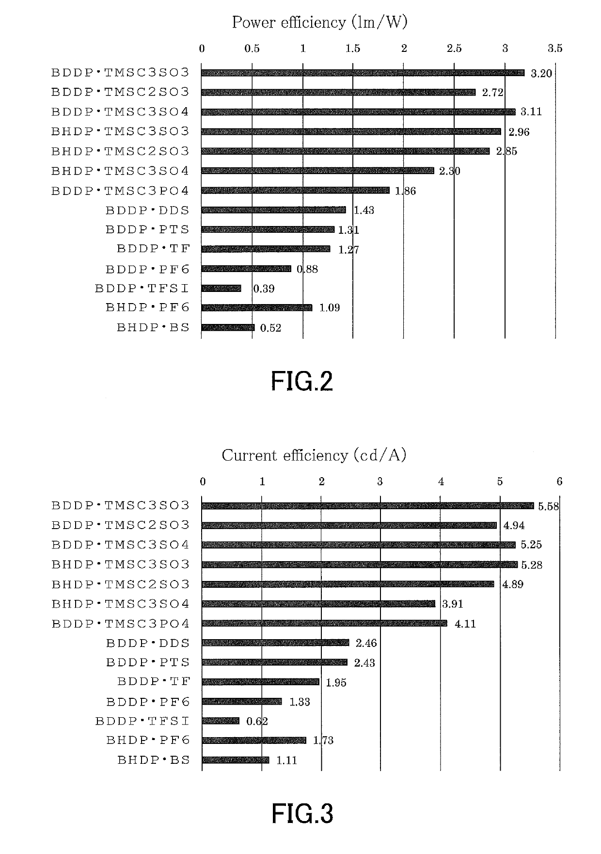
[0118]Light-emitting electrochemical cells were produced in the same manner as in Example 1, except that ionic compounds listed in Table 1 were used instead of BDDP⋅TMSC3SO3, and the light emission characteristics of the light-emitting electrochemical cells were evaluated. It should be noted that the number of moles of the ionic compound per 1 g of SY was the same as in Example 1. The ionic compounds were synthesized by the methods referred to or described above.

example 8

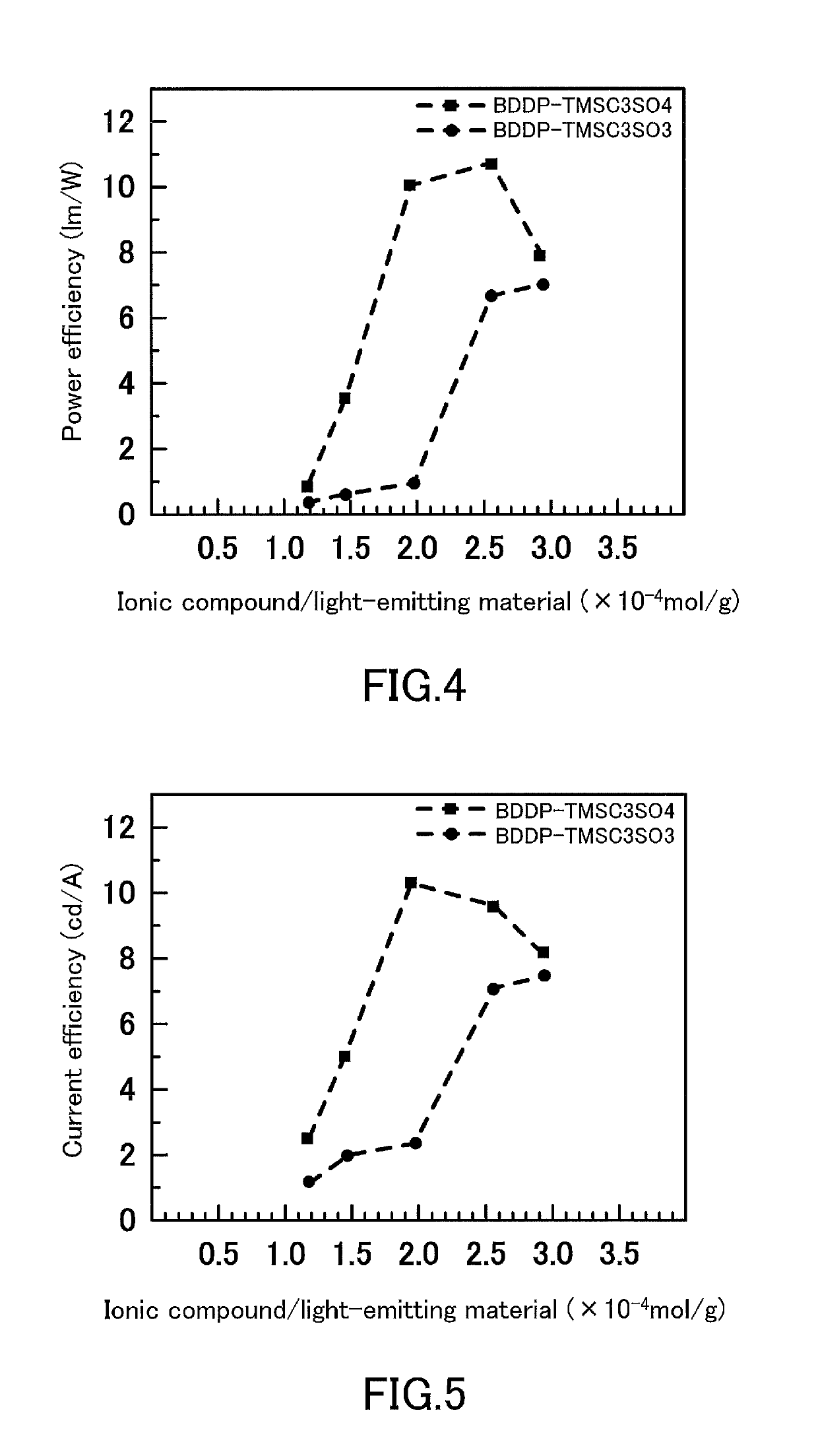
[0126]Light-emitting electrochemical cells were produced in the same manner as in Examples 1 and 3, except that the numbers of moles (mol / g) of BDDP⋅TMSC3SO3 and BDDP⋅TMSC3SO4 added per 1 g of SY were 1.2×10⁻⁴, 1.5×10⁻⁴, 2.0×10⁻⁴, 2.6×10⁻⁴, and 2.9×10⁻⁴, and the light emission characteristics of the light-emitting electrochemical cells were evaluated. The results for the maximum light emission efficiency achieved in the measurement are shown in FIG. 4 and FIG. 5.

[0127]From FIGS. 4 and 5, it can be concluded that the appropriate amount of the ionic compound added to the light-emitting material, as expressed by the number of moles (mol / g) of the ionic compound added per unit weight of SY used as the light-emitting material, is generally about 1×10⁻⁴ to 4.5×10⁻⁴, and that the optimal amount is about 1.5×10⁻⁴ to 3.5×10⁻⁴ for BDDP⋅TMSC3SO4 and about 2.0×10⁻⁴ to 4.0×10⁻⁴ for BDDP⋅TMSC3SO3. For both BDDP⋅TMSC3SO3 and BDDP⋅TMSC3SO4, it was confirmed that, although precise measurement was no...


PUM

PropertyMeasurementUnit
thicknessaaaaaaaaaa
thicknessaaaaaaaaaa
thicknessaaaaaaaaaa

Abstract

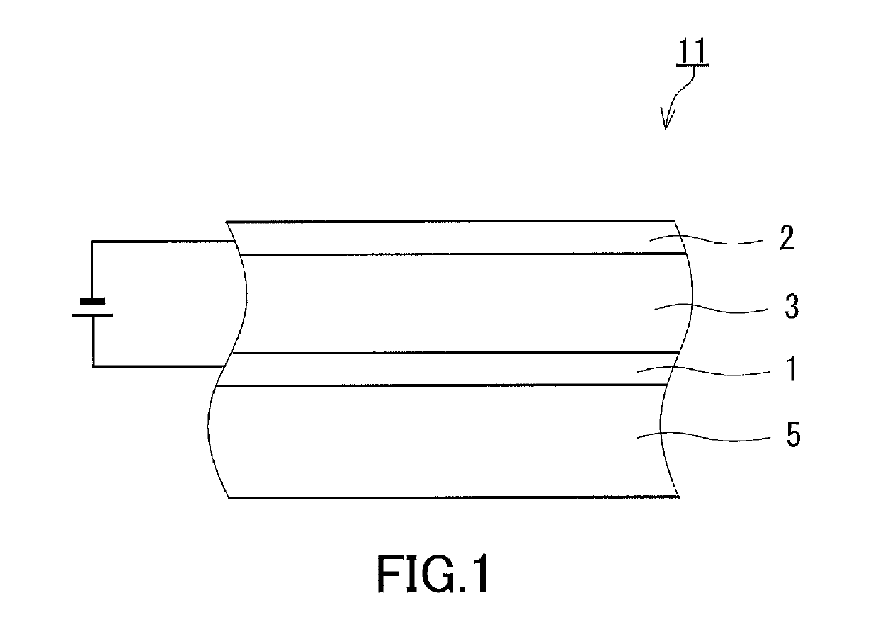
Provided is a light-emitting electrochemical cell including a light-emitting layer 3, a first electrode 1, and a second electrode 2, wherein the light-emitting layer contains an ionic compound and the ionic compound contains an anion having a silicon atom. The anion has a silicon-containing group represented, for example, by SiR1R2R3 (R1 to R3 are all bonded directly to Si) and an anion group. The anion group is represented, for example, by —SO3−, —OSO3−, or —OP(OR0)O3−. R0 to R3 are each independently an alkyl group having 1 to 4 carbon atoms. Two alkyl groups selected from R1, R2, and R3 are optionally bonded to each other to form an alkylene group having 4 or 5 carbon atoms and constituting a cyclic structure together with the silicon atom.

Description

TECHNICAL FIELD[0001]The present invention relates to a light-emitting electrochemical cell having a light-emitting layer containing an ionic compound such as an ionic liquid together with a light-emitting material.BACKGROUND ART[0002]Organic electroluminescence (organic EL) devices are thin, lightweight self-luminous devices requiring no backlight and are used in the field of displays and lighting equipment. However, organic EL devices involve a multilayer structure sandwiched between a pair of electrodes, the multilayer structure being constituted by a hole injection layer, a hole transport layer, a light-emitting layer, an electron transport layer, and an electron injection layer, all of which are extremely thin layers. Thus, organic EL devices pose difficulty in manufacturing cost reduction and are likely to suffer defects such as leakage.[0003]Light-emitting electrochemical cells (LECs) are self-luminous devices including a light-emitting layer made of a light-emitting material...

Claims


Application Information

Patent Timeline
Patent Type & Authority Applications(United States)
IPC IPC(8): F21K2/08H01L51/50C09K11/07H10K99/00
CPCH01L51/5032F21K2/08C09K11/07C09K2211/18C09K2211/10C09K11/06H10K85/40H10K50/135H10K50/11
Inventor MURATA, HIDEYUKITAKAGI, MANATOSUZUKI, TAKATOMASUDA, GENYUYAMA, KANAKO
Owner JAPAN ADVANCED INST OF SCI & TECH
Learn More