Electronic device for liquid immersion cooling, power supply unit, and cooling system

Active Publication Date: 2019-10-17
EXASCALER
View PDF8 Cites 2 Cited by
  • Summary
  • Abstract
  • Description
  • Claims
  • Application Information

AI Technical Summary

Benefits of technology

The present invention provides a new power supply unit for electronic devices, such as servers, that can be used in a liquid immersion cooling system. This new power supply unit eliminates the need for a separate power supply cable, simplifies cable wiring, and improves maintainability of the electronic device. It also reduces power loss and improves cooling efficiency, allowing for longer periods of operation without overheating. Additionally, the power supply unit can be adapted to the HVCD system for even greater power loss reduction. The cooling tank design with an open space allows for quicker heat transfer and reduces vibration. The cooling tank with a simplified sealing structure is also provided for improved maintainability.

Problems solved by technology

The power for cooling operations accounts for approximately 45% of the power consumption of the entire data center.

Method used


Image

  • Electronic device for liquid immersion cooling, power supply unit, and cooling system
  • Electronic device for liquid immersion cooling, power supply unit, and cooling system
  • Electronic device for liquid immersion cooling, power supply unit, and cooling system

Examples


Embodiment Construction

[0064]Preferred embodiments of the electronic device, the power supply unit, and the cooling system according to the present invention will be described, respectively in detail referring to the drawings.

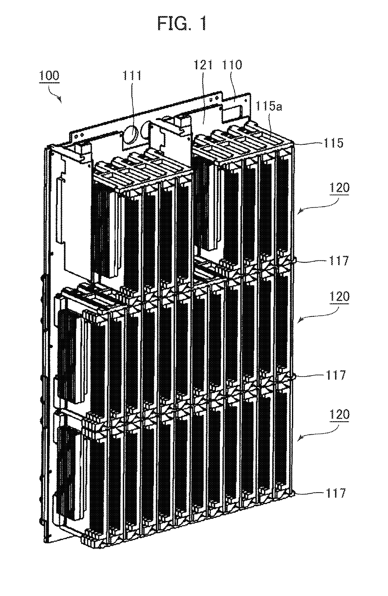
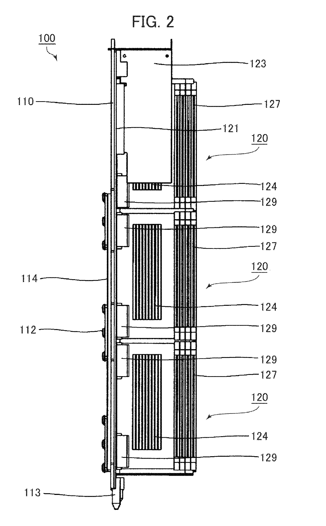
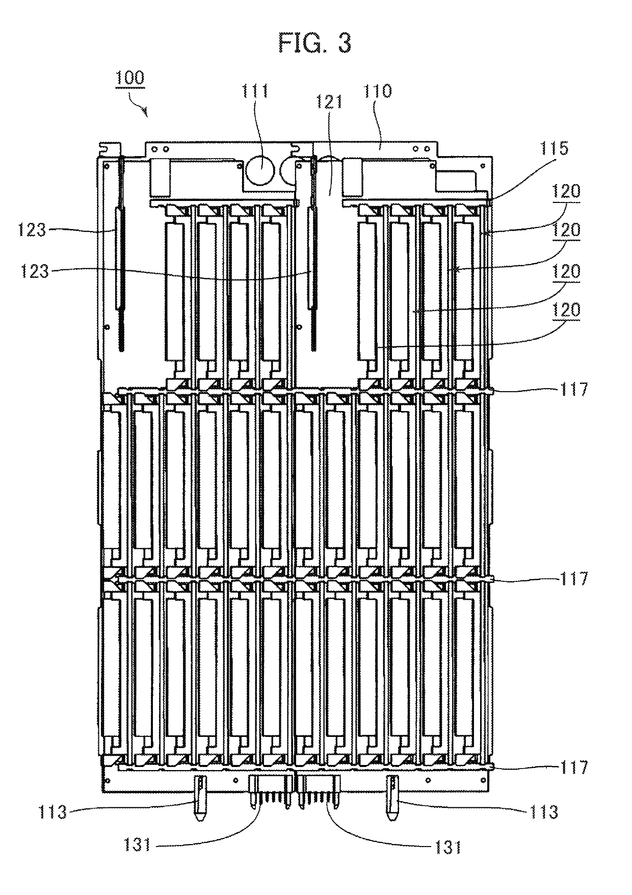
[0065]Referring to FIGS. 1 to 4, an electronic device 100 according to an embodiment of the present invention will be described. FIG. 1 is a perspective view of the electronic device 100 according to the embodiment of the present invention. FIG. 2 is a side view, FIG. 3 is a front view, and FIG. 4 is a partial assembly view. The electronic device 100 is immersed and directly cooled in the coolant filled in a cooling apparatus to be described later. The electronic device 100 includes a backboard or a frame structure 110 (hereinafter simply referred to as a “backboard 110”), a plurality of module substrates 120, a carrier substrate 121, and a plurality of supporting plates 115, 117. As shown in the drawings, a power supply unit is eliminated from the electronic device 100. The power su...


PUM


Abstract

Provided are an electronic device and a power supply unit, both of which are immersed and directly cooled in a coolant filled in a cooling apparatus. The electronic device includes a carrier substrate having a voltage input terminal for supplying a DC voltage for the electronic device, a plurality of module connectors arranged on one surface of the carrier substrate, a plurality of module substrates, a plurality of supporting plates for holding both ends of the respective module substrates, and a supporting member for supporting the carrier substrate. The voltage input terminal is electrically connected to a voltage output terminal of the power supply unit. Each of the module substrates includes a module connector plug electrically coupled to each of the module connectors. The supporting member supports the carrier substrate so as to be positioned at the upper part of the power supply unit mounted on the bottom of the cooling tank of the cooling apparatus upon electrical connection between the electronic device and the power supply unit. The power supply unit includes a unit substrate, a voltage step-down device mounted on the unit substrate, and a stage to which the unit substrate is fixed.

Description

TECHNICAL FIELD[0001]The present invention relates to an electronic device and a power supply unit. More specifically, the present invention relates to an electronic device immersed and directly cooled in the coolant filled in a cooling apparatus, and a power supply unit. The present invention also relates to a cooling system using the electronic device and the power supply unit. The electronic device described in the specification generally denotes the one required to exhibit super-high performance and stable operation while generating high heating value such as a supercomputer and a data center. However, they are not limited to those described above. The power supply unit refers to a unit including a voltage step-down device for stepping down a high voltage input from an external power supply (for example, DC380V, AC200V) to a DC voltage output for the electronic device (for example, DC48V (including DC47.5V), DC12V).Background Art[0002]Power consumption is one of the essential fa...

Claims


Application Information

Patent Timeline
IPC IPC(8): G06F1/20G06F1/26H05K7/14H05K7/20
CPCH05K7/20236H05K7/20263H05K7/14G06F1/20H05K7/20281G06F2200/201G06F1/26H05K7/20763H05K7/20781H05K7/20818
Inventor SAITO, MOTOAKI
Owner EXASCALER
Why Eureka
Try Eureka